[Back to Home Page]
www.RomanBlack.com
Cool things I have made
Just some short descriptions...
Roman Black - started 12th Feb 2008 - updated 6th Dec 2010
Stepper motor 1-hand clock
Sept 2010.

I built this one hand analog clock simply by putting a hand on a stepper motor,
then using a LiniStepper v2 and my own firmware to make the stepper motor
turn exactly one revolution every 6 hours. Because the LiniStepper PCB gives
linear smoothed microsteps the clock hand moves very smoothly (and slowly!).
The clock is synced to mains frequency and keeps perfect time.
12 o'clock and 6 o'clock are both at the TOP of the dial.
The clock body and hand are CNC cut from acrylic plastic and the stepper motor
was a junk one pulled from an old bubblejet printer.
This complete project
has its own page and includes
free open-source PIC asm firmware for PIC 16F628A.
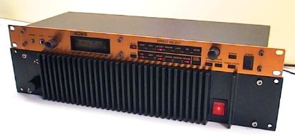
Closed-loop PID router speed controller
Aug 2010.

This is a speed controller to use on my CNC machine, it is closed loop
and uses a optical RPM sensor on the router spindle shaft and my own
specialised PID math system to control the router RPM.
Hardware consists of a large IGBT for mains power switching, a lot of filtering
and mains components, fan etc, and a PIC micro as the brain. I used a
Shift1_Tacho PCB and a large
format 16 char LCD display to provide a nice accurate tacho.
It also has a 10 LED bargraph display that shows the percentge power
being fed to the router motor.
The original had PWM switching at 1200Hz but I soon changed this to mains
phase angle switching to make it quiet and reduce stresses on the router
windings as the PWM switching was very harsh. Ultimately my original
design was over-engineered and too complex, and was greatly refined at a friends
request to eventually be released as a commercial product under license;
you can see it at www.SuperPID.com
and please feel free to buy one, I make a few dollars for each one sold. :)
Big Dummy
Mid 2010.
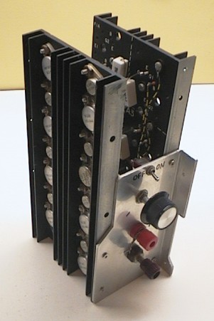
I was building a friend a huge 12v battery charger for his solar installation
and needed a dummy load to test the output. Big Dummy is a 500W dummy load
for testing high power 12v to 48v supplies at up to 30 amps.
It is not pretty, because it was built in a hurry from a couple of old surplus
1960's heatsinks that already had 8 big TO3 and darlington drivers on each sink.
This setup was typical of big linear power supplies of the time. These are
good quality sinks and had nice teflon high temp wire etc on them, I pulled
the sinks off some Vietnam era military power supplies in a junkyard about
15 years ago and it was about time I put them to use. For 45 year old equipment
all the parts are still in perfect condition and fully working.
I bolted both sinks vertically to a 3mm aluminium plate and added a new pot
and knob for the current adjustment and a switch to turn the biasing on/off
so I don't have to pull a plug with 30 amps going through it. In total there
are 15 TO-3 transistors and 15 smaller driver transitors as a massive parallel
darlington with a third driver trasistor (trilington) and the pot. There are
15 1ohm 5W emitter resistors to stabilise the current. I use a desk fan to cool
it when sinking currents above 20 amps.
Human powered lantern
Early 2009.

This was a fun project. It is a very simple lantern, you turn the handle and
the white LED lights up, and it also charges a 1 farad supercap which lights
the LED for a few of minutes after cranking.
This is actually quite a sophisticated high-efficiency design for a number
of reasons;
1. The dynamo is very efficient and low drag, it is a VCR 3-phase low-RPM capstan motor
2. The dynamo 3-phase output is rectified by 6 low drop schottky diodes
3. The light source is a 1W high efficiency LED
4. The handle is optimised for good speed and kinesthetics
5. The structure is robust, solid acrylic and stainless steel screws
6. It produces a lot of light for the turning effort (unlike highly geared torches!)
7. There is a low drop out micro regulator to fix LED current (2 settings)
8. All bearings are large stainless shafts for long life
9. There is a single gear ratio 4:1 for good energy efficiency and simplicity
The lantern is very pleasant to use, unlike noisy cheaply made commercial human
powered torches. It has 2 sitting positions, one lights the table, the other is
tilted up 45' and lights an area of the wall. I designed and built this after many
power blackouts and each time finding the torches all had flat batteries...
That has never been a problem with this beauty.
My regulated "Gainclone" hifi amplifier
Jan 2009.
I used a 1980's power amp (P.A. amplifier) case which had a great heatsink
front panel and huge beefy power supply. I installed 2 "Gainclone" style
high performance audio amps and built a regulated low noise power supply.
This project now has its own page.
RC Servo tester - exerciser
Early 2007, web Feb 2008.
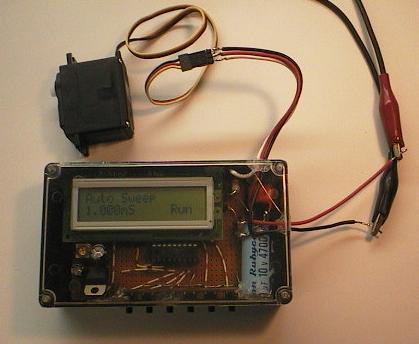
This gadget drives any RC Servo and allows the servo to be tested,
positioned or exercised (run in). Sometimes I work with RC Servos for
robotics and this unit has been very handy!
Made from junk box parts, the only new part I think was the neat
plastic zippy box with clear lid! Uses PIC 16F628 and a 16x2 line LCD.
The 6 button assembly was from an old TV set I think.
DC power is from my bench supply so I can use its volt and amp meters
when testing the servos.
The unit has its own +5v regulator built in for the PIC and LCD.
Everything was thrown together with hot-melt glue as I was in a hurry!
It has a few modes, manual and auto sweep modes. In auto sweep the
unit sweeps the servo full scale every second, ie from 1.0 mS to 2.0 mS
pulse width. This is handy for running in mechanisms and heat testing etc.
In the manual modes the servo can be moved in very small amounts or
larger amounts depending which button is pressed.
The unit has accurate timing (driven from 8MHz xtal), and at all times
it displays the servo pulse width in actual milliseconds and
microseconds. Smallest adjustment is 5 microseconds. This allows
the servo to be positioned to an exact angle, then the mS value
(ie 1.245 mS) read from the display and that can be used later in
robotics software for that same servo etc. It also lets me test servos
and rotate them well past the "proper" limits to find their exact
travel-limits.
Yes I know that some of the Servo companies sell similar servo testers
to this, but they are quite pricy! This one was built for a few bucks
to suit my exact needs, and I can reprogram the PIC at any time to add
new modes and features.
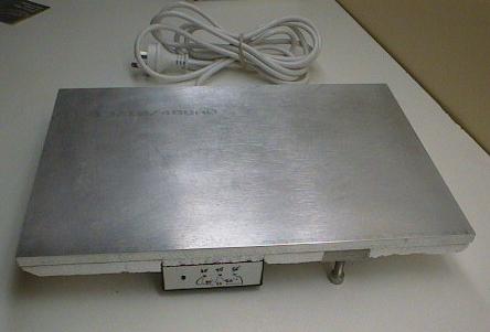
Precision temperature controlled leveling hotplate
Mar 2007, web Feb 2008.
This is an electric hotplate, about 400 x 300 mm size. It is made from
12mm (1/2") thick aluminium plate which has been surface-ground to a very
flat surface. It can be "levelled" by adjustment of 2 of the 3 feet,
which are stainless bolts and can simply be rotated to adjust the height.
I positioned the feet in a right-angle triangle so one bolt changes "roll"
and one changes "pitch".
It has 1 button and 3 leds (see below). By pressing the button the PIC micro
(inside the black zippy box) sets the hotplate to one of these 6 heat
settings;
35'C, 40'C, 45'C, 50'C, 55'C, 60'C.
These temperature settings are very useful for hardening and curing
molds and epoxies etc, equally useful is the precision flat-ground
levelled surface.
Clever stuff; To get the thing to maintain a very exact temperature
even with its large thermal mass, I developed a "forced time-constant"
closed-loop temperature control algorithm. The PIC micro using this
algorithm keeps the hotplate within 0.2'C of the desired temperature
which is a big improvement over the large thermal ripple and laggy
response caused by a normal closed-loop temp control.
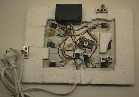
With the bottom cover removed you can see the transformerless design.
The 240v 50Hz AC mains is rectified
and the resultant 100Hz 300v DC feeds the 4 main flat pack transistors. These
act as transistors (ie controllers) and they are ALSO the heating elements!
They are 1500v 5A TV h-out transistors with internal protection,
so they are much more rugged than required, to give long life. They are
also a fully insulated package type, because the metal hotplate is
grounded! All the wiring and parts are secured with screws and
high-temp silicone so nothing comes loose.
The PIC micro (inside the black control box) is powered via 2x 10 watt
resistors into a 16v 5 watt zener diode and a big filter cap. This gives
16v DC at about 25mA, reasonably regulated.
There is a +5v (low quiescent current) secondary regulator inside the
box that gives a very stable +5v dc for the PIC, leds and temp sensor.
The PIC is a little 8-pin 12F675 running 4MHz on internal RC osc. The
temp sensor is a DickSmith 100k NTC Thermistor, clamped and epoxied to
the hotplate next to one of the 4 big power transistors. My special
algorithm allows the use of a "crude" thermistor and still gives very
good temperature control.
The hotplate heaters run at a forced max of 40w each (160w total). They run
in constant-current mode with +4v on their base and an emitter resistor.
So each heater produces the same amount of heat. I positioned the 4 so
the heat is equally distributed over the entire hotplate.
Another large transistor acts as a darlington common driver and gets the
4 drive currents from the mains, the pic only needs a couple of mA to
operate all 4 heaters.
In use the heaters are ON about 1/4 of the time at 35'C and
about 2/3 of the time at 60'C, 160w was just right for good temp
regulation and gives a reasonably fast warm up of 5 to 10 minutes.
- end -
[Back to Home Page]