[Back to Home Page]
www.RomanBlack.com
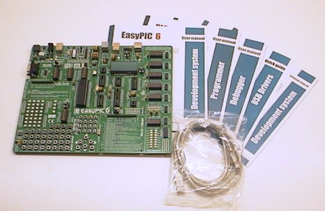
The EasyPIC6 from MikroElektronika
I review the EasyPIC6 PIC development board
- 11th Oct 2009.
What is it?
EasyPIC6 is a fully contained development board that you can use
to program a PIC microcontroller and design and test PIC projects.
The EasyPIC 6 contains many devices like displays and pushbotton controls
that easily interface with the PIC.
History
I've had my EasyPIC4 for a couple of years now, and it has been
such an excellent PIC development board. It has done a ton of hobby and
personal stuff and even been used to develop a number of commercial
PIC-powered products.
When MikroE brought out the EasyPIC5 I thought of getting one but it
didn't do much more than my EasyPIC4, the main addition was a touch
screen for the graphics LCD display (nice!) but that feature alone was
not enough to make me upgrade.
Now the EasyPIC6 is here, and all I can say is WOW. I keep an eye on
MikroElektronika's hardware and I had been waiting for them to switch
to a SMD (surface mount) approach, knowing that it would allow them
to add a LOT more hardware onto their already packed development boards.
The moment I saw the EasyPIC6 it was obvious they had taken the leap. It has
all the small discretes (resistors, caps, LEDs etc) replaced with smaller
SMD devices. The extra space that is saved has been put to good use,
with some great new features added.
On board USB programmer and ICD
Like all the MikroE hardware the EasyPIC6 has fully built in PIC programmer
using an easy USB cable to your PC. The PICFlash programmer circuitry
also has the powerful feature of fully switching the PGD, PGC and MCLR
pins, so these can still be utilised in your project. This is an excellent
system that lets you have full use of ALL the PIC pins at all times
with the PICFlash only taking control of them during programming itself,
and that is all fully automatic.
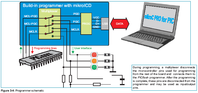
The PICFLash also has a built in ICD hardware debugger that runs under
the same easy USB lead and is included as standard in all the MikroE
compilers. New for EasyPIC6 is a separate ICD port, so you can even use the
Microchip ICD2/ICD3 with your EasyPIC6 if you prefer that debugger.
For beginners the PICFlash programmer (that is included onboard
the EasyPIC6) is very easy to use. You write your source code in the
MikroC PRO compiler on your PC, then press a button, and the EasyPIC6
automatically porgrams your PIC (takes about 10 seconds) then your
project instantly starts working.
This allows for very fast building and modifying a project.
(Note! You are not forced to use MikroE compilers, you can use
any compiler or assembler you choose and just use the free PICFlash
windows software to load the .HEX file into the EasyPIC6).
Now for the comparison!
I will compare the new EasyPIC6 to the EasyPIC4.
I resized the photos to about the same scale, as you can see the
EasyPIC6 is a bit bigger.


New additions for the EasyPIC6;
Switchmode high efficiency 5v regulator
Onboard 2x16 char LCD COG (Chip On Glass type)
MCP23S17 16bit port expander IC (gives 2 more 8bit ports!)
Socket to connect an external ICD ie Microchip ICD2 or ICD3
Backlight power (and switch) for LCD and GLCD displays (but not COG LCD)
16 button standard numerical keypad
6 button menu style keypad; 4 arrows, enter, cancel
Safety resistor and jumper for all port buttons
Power on/off switch (was also on EasyPIC5)
Touchscreen for graphic LCD (also on EasyPIC5)
DIP switches allow individual selection of port pin pull-ups (also on EasyPIC5)
DIP switch to setup RS232 port pins (also on EasyPIC5)
Features removed from the EasyPIC6;
4 digit LED 7-segment display
Reduced from 2 ADC trimpots to only 1 ADC trimpot
Evaluation of the changes...
The change to smaller SMD components and the larger overall PCB size
has allowed lots of nice changes. As a hardware designer myself who
has worked with through-hole and SMD designs I can see many of the
MikroE design team's thought processes, I can almost see their
enthusiasm in the design... "Yay! Now we've got room to add a switching
power supply... AND a 16 button numeric keypad if we shrink the buttons
a bit!"
This is wonderful to see. MikroE have always made exceptional development
hardware cramming lots of very practical features into compact and
inexpensively priced boards. I've been wondering for years what their
excellent design team could make if they switched to the smaller SMD
components, and was delighted to see them taking this new step.
The attention to detail in the SMD design of this board is amazing,
it is really a work of art. In many SMD designs of my own the parts
were placed for compactness, or easier assembly, or easier track routing.
But the EasyPIC6 SMD design appears to have been done to be attractive
and orderly as a very high priority! At first I thought this was
due to a naivety of the design team, being a bit new to SMD...
But looking closer the SMD design seems more a joy of finally being
unleashed on SMD and a genuine desire to do a really beautiful SMD
layout. It's almost like they have a reverence for the layout.
Just check out the sheer beauty of this SMD layout;
Some practical improvements were needed to the EasyPIC4 and EasyPIC5 designs.
My EasyPIC4 never had a power switch, and the 7805 voltage regulator used to
get very hot when I used the EasyPIC4 in the workshop from an external 9v supply
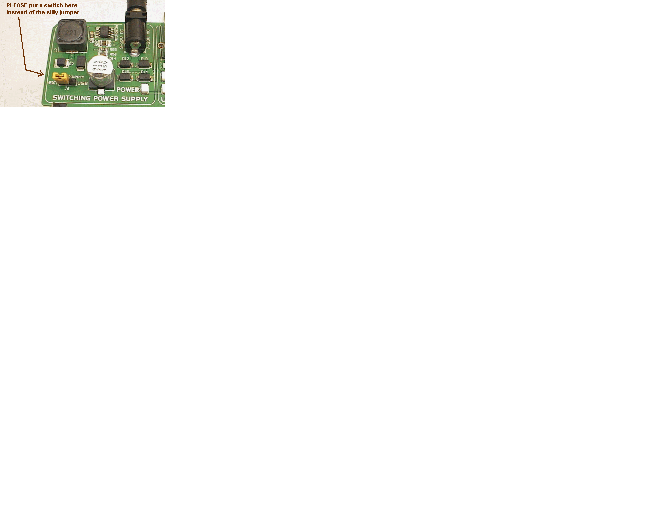
that runs at about 11v DC. Also the jumper used on the EasyPIC4 and EasyPIC5 to
change between external power and USB power was annoying. As my EasyPIC4
got a lot of use I re-engineered these features myself, by soldering a
switch instead of the jumper selector, AND by bolting a solid block
of alloy to the 7805 to keep it cool (see below). Fortunately MikroE
were on top of these issues and all has been fixed now in the EasyPIC6!
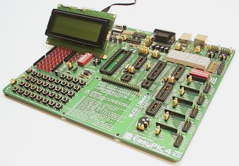
My trusty old modified EasyPIC4;
Now the new EasyPIC6 HAS a power switch and it comes standard
with a high-efficiency switchmode power supply!
I also like the many small changes on the new EasyPIC6.
Some, like the switch to black DIP switches instead of red make the
EasyPIC6 much more attractive.
Other small changes are more functional, like improving the jumpers
that select the MCLR options for the PIC chips and adding little
knobs to the trimpots so you don't need a tiny screwdriver everytime
you need to adjust the LCD contrast or ADC trimpot.
Going backwards?
Losing the 4 digit LED 7-segment display may disappoint some people.
But really it is obsolete technology for anything other than large
clocks! A text LCD is much more useful
as it has 32 digits (not 4) AND can show text as well as numbers!
In the last 2 years I haven't used my EasyPIC4 LED 4 digit display other
than playing with the examples. A 4 digit clock is such an easy project
it may not require LED development hardware anyway. I really don't
mind losing the LED display, but then I've got an EasyPIC4 with that
feature so maybe I'm not the best person to comment on the loss
of the LED display. :)
I was a bit unhappy to see the 2 ADC trimpots reduced to
just one. Some ADC projects will make use of 2 voltages, especially
if working with the PIC comparators. But then again, I have only ever
used one of the ADC pots on my EasyPIC4 even though it gets used a lot.
Two is definitely better than one.
Overall there really isn't much to complain about. It's just a huge
step forward, the best development board they have ever made and
in my opinion the best development board in the world.
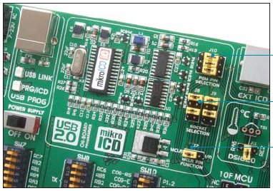
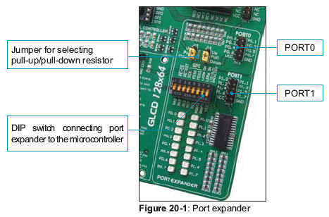
Port expander and COG display
These are great features! The port expander gives 16 more pins you can use,
and it also drives the COG 2x16 char LCD display.
The port expander IC is a Microchip MCP23S17.
This gives 2 more ports of 8bits, so it gives 16 more pins that your PIC
can use. It is a very powerful IC, probably a little overpowered as I
would have just used a 8bit shift register or something... But the
MCP port expander gives you total control of every one of the 16 pins,
to make them inputs or outputs as needed. It even has an internal
interrupt so it can sense pin changes etc. The PIC connects to the
MCP port expander via 5 (SPI) pins, on PORTA 2,3 and PORTC 3,4,5.
This means to use the port expander and COG display you need to
have a PORTC, which *generally* limits you to the 28 and 40 pin PICs.
(Note! I have a workaround for this, further down the page)

The COG LCD display is just another 2x16 char LCD using the
standard Hitachi 44780 internal chipset. My old EasyPIC4 had a LCD 2x16
connector (as does the EasyPIC6) but the benefit of the COG is that
it is A SECOND LCD display. This was a big part of my decision to get
a EasyPIC6. I develop a lot of machine controllers etc using a PIC, some
buttons and a display. This has always been a strength of the EasyPIC
series, you can quickly put together an application to make a useful
controller with a text or graphics LCD. Having a second LCD display
that only ties up 5 PIC pins is a very nice feature.
So you can design your product with the LCD in the exact use of the
final application, AND also have a "debug" type display that
will show you exactly what you want to see, with the data formatted
the way you need and operating in real time unlike any other ICD
option. This was especially attractive to me as I do power
controllers that need exact fast timing for PWM motor control
and SMPS control etc, so I can get the PIC to write to the COG
display at the times when I know the PIC is free, it's very handy
to be able to display internal values under your own control,
even doing calculations on the values and displaying some useful
data during run time.
In the past I have had to do this on the application LCD, but
that means messing up the application LCD code and/or not being
able to see the application LCD menu etc.
The MikroE team have thoughtfully put the standard LCD in 4bit mode
on PORTB (which is a change from my EasyPIC4 where it is on PORTD) so
they have obviously anticipated using the LCD (or GLCD) at the same time
as the COG LCD. Yes you can use them at the same time. This is very pro,
and very sexy.
Summary of the port expander and COG LCD.
These really are the big new features for the EasyPIC6. I really like
having the ability to run the COG LCD at the same time as another
LCD. I would have preferred not to need 5 PIC pins to drive a
display, it could have been done with a 74HC595 8bit shift register
and 3 PIC pins. That's a very low cost option AND it would have left
the nice port expander IC unused. Also, it would have been great
to have COG LCD capability with small PICs like an 8pin PIC or even
a 18pin PIC. But that's can't easily be done as the present setup
requires PORTC. I think MikroE should seriously look at using a
cheap shift register IC and some DIP switch options, so the COG LCD
can be used from any of the PICs with just 3 pins AND leave the
full port expander available. That would rock.
The port expander is a really nice IC. It is a Microchip IC
and like Microchip's PICs it uses many of the standard features
for its port pins as the PICs use for their port pins. Things like
internal pullups, interrupt on change, bidirectional control, etc.
It really is like sticking another 16 pins on your PIC. Good stuff!
If I was to find fault with the port expander it would be to
question the choice of SPI. The whole point of a port expander
is to add more pins to your PIC but the SPI version requires
5 PIC pins (even 7 PIC pins for interrupt use). The same MCP
chip is available in I2C version that only needs 2-3 PIC pins to
drive it. I suspect MikroE chose the SPI version because it is
a little easier to interface, and maybe a bit faster. I'm not
totally sure but *maybe* it would have been better to use the
I2C version as it could have been used on any of the PICs like
the 8pin 12F675 etc which would have opened up many options.
One of the first things I did with the EasyPIC6 was write my own
SPI port expander code routines. I trimmed the code down to the
absolute minimum needed to write to the MCP expander chip to
drive the outputs, and I also wrote stripped-down COG LCD
code. My code is many times smaller than the MikroC PRO
library routines, so you can use it in small projects where
you want to add COG LCD to the project but don't have much
spare rom. Also my routines work fine on the old MikroC
and don't require MikroC PRO. Likewise they can be changed to
work with any 4 PIC pins and will convert quite easily to
PIC assembler if you like.
You can get my free MikroC EXP and COG routines here.
The new ICD connector!
I completely missed the importance of this new connector until I
was writing this review! The connector didn't interest me initially
because I don't use the Microchip ICD so I don't need to plug one in.
But this ICD connector can ALSO be used to send programming data out!
This means the EasyPIC6 can be used as a programmer, to program other PICs
including ICSP (In Circuit Serial Programming) of a PIC on your own
hardware.
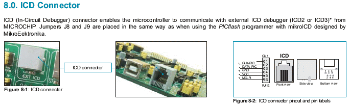
OK, many people (including myself) have already been using their EasyPIC's
as programmers, by making a plug that goes into the PIC socket, then
wires coming out to the target application. But now it should be possible
to plug a neat lead into the ICD connector, and into your target board,
and use the EasyPIC6 as a PIC programmer! Sweet.
The new keypads
Why add two new keypads? After all, there is already
a pushbutton for every PIC pin (like in all MikroE dev boards).
But these 2 new keypads on the EasyPIC6 are a nice feature. Developing a
LCD-based menu system is much easier using the arrow keys in a
nice diamond shape.
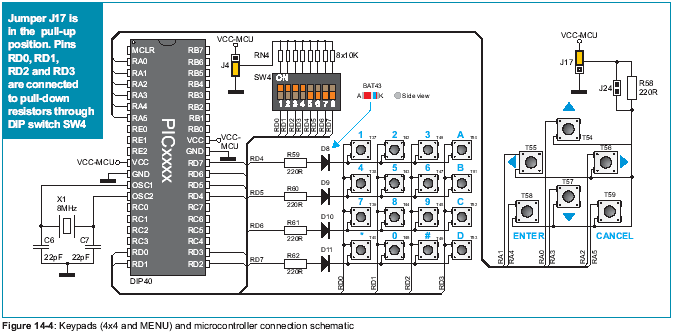
Also, the 4x4 keypad is not just a shape, it is a properly setup
4x4 multiplex with all the necessary diodes and resistors, then
connected to 8 pins on PORTD.
So the keypad multiplexing code can be written and tested ready for
the final hardware. Before the EasyPIC6 all you could do was wire up an
external keypad module and connect to the port edge connectors.
The touch panel
I'm a bit sad now because I forgot to order the touchpanel! I already
had a couple of GLCD (graphic LCD) and really wanted to play with
the touchpanel but that will have to be a job for another day.

Touchpanels are very cool. Up to now, not many PIC development boards
supported this new technology and it's great to see MikroE making this
a standard feature on their dev boards.
The touchpanel is a resistive device made from clear film, it acts like
a potentiometer. +5v and 0v are applied to the right and left sides
of the screen and when you touch it that acts like a "wiper" of a pot
and makes a voltage based on the position. Then the system is repeated
for the top to bottom. The PIC just needs to check the right/left voltage,
then check the top/bottom voltage, and then it knows the exact position
where the screen was touched. Obviously this can be used to press
virtual "buttons" or icons on the screen (like a Pocket PC) and to
create more interesting controls like sliders to adjust values etc.
I'm looking forward to doing some touch panel projects.
Modifying the EasyPIC6
I've only used my EasyPIC6 for a few days, for a couple of hours a day.
So far the only modification I have done is to bend the COG LCD screen
up at an angle of about 20 degrees. Since the COG display doesn't have
a backlight and the character size is a little small, it is MUCH
easier to read when pointed more at my face. I was worried about
breaking it, after all it is glued together out of very thin glass!
However I was able to slowly bend it up by putting a plastic ruler
under it to act as a support/lever and VERY slowly bending it forward.
This bends the row of legs slightly. I still need to glue a small
support under it but for now I am very happy with the increased
readability.
(Note! If you bend yours, and it breaks... Don't blame me!!)
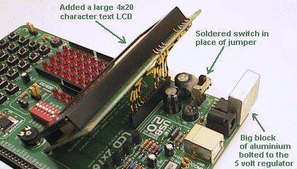
The other mods I did on my EasyPIC4 and will do again to my EasyPIC6 are;
Put a small slide switch on the power supply selector
Add a long-wires connector on a 4x20 text LCD (to mount it at an angle)
Add indents to sockets with soldering iron for easier PIC removal
I can see more on a 4x20 LCD than on a 2x16!
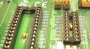
Melting a groove in each end of the PIC sockets, for quicker PIC removal;
What additions/changes does the EasyPIC6 need?
As good as the EasyPIC6 is, *in my opinion* there are a few things that could
be done to make it really fantastic...
1. It needs a beeper! The EasyPIC series of dev boards are really useful
for developing applications with buttons+LCD+menu, like machine controllers
or test equipment etc. But with buttons+LCD+menu you NEED a beeper. Almost
every LCD application I do gets a beeper to make shorts beeps on keypresses
and longer beeps on menu change or errors etc. Since 5v piezo beepers are tiny,
can be bought for a few cents in bulk and only need one PIC pin it really
is a very high benefit to cost ratio. Are you listening MikroE? Add a beeper!!!
2. The LEDs are too bright... It's great that the EasyPIC6 uses high
efficiency SMD LEDs. The fact that they use only 1mA and are very bright
is good, but they are too bright. It's painful looking directly at the LEDs,
and you usually have to do that to read the PIC pin labels written next
to the LEDs to see which LED is lit up. I tried adding a white sticker over
the LEDs that improved the situation by making them darker, BUT then the
labels cannot be read. This is basically a zero-cost change on future
EasyPIC6 production runs, just change the LED resistors to drop the current
to 0.25mA or so. Maybe less, as they are still VERY visible on 1:10 duty
cycle.
3. Go back to 2 ADC trimpots. This is a power-user feature.
I'm sure lots of people (like myself) use the EasyPIC dev boards to make
power supply controllers and battery charge controllers etc and 2
trimpots is very handy. There is plenty of PCB space to go to 2 pots,
even if they are a smaller SMD type, and replace the existing 5-way
jumper with a 8way DIP switch for 2 trimpots.
4. Change the power supply selector to a switch.
I think this one is obvious. There is not that much cost difference
between a switch and a jumper, but the switch is SO much better to
use. It is also more reliable, jumpers can get loose and are not
great for carrying any significant current. I often program my EasyPIC
in the computer room (with USB power), then take it out to the
workshop and connect it to external power when it is being used to
generate a signal or control some equipment. I can't live with
a silly jumper, it will be the first thing to go on my EasyPIC6.
5. Add a connector so you can program external PICs with the EasyPIC6.
Whoops! You already did this! Looks like the new ICD connector can be
used to program PICs off board. Absolutely fantastic. Thank you!
6. Add a medium sized I2C eeprom memory chip.
These still cost a couple of dollars, for say a 8pin
512kbit eeprom. But it wouldn't cost much in PCB space as the
8pin SMD device is very small. Or maybe just add a 8pin DIP socket
so the user can insert their own choice of eeprom at their expense.
It would allow a LOT of options, like development of datalogger
applications (the EasyPIC6 is perfect for that!) for storing incoming
streams of serial data, or even storage/generation of complex
waveforms like using the EasyPIC6 as a storage oscilloscope or using
the EasyPIC6 to playback speech samples when buttons are pressed.
For the small cost, an eeprom is really worth adding, provided it
has lots of storage, like 512kbit or larger.
7. A little 555 oscillator.
I made one on a tiny PCB and have used it so much with my EasyPIC4!
It's just a 555 timer oscillator that generates a frequency,
with a trimpot to set the frequency and a range switch.
It gets used all the time designing tachos and speed readouts
and frequency readouts, testing dataloggers etc. Now MikroE have
SMD capability this could be added in about the same PCB space
as the ADC trimpot takes up.
8. Add a shift register IC to drive the COG LCD.
Some people might disagree with me on this one so I'll walk through the
logic of it; a) The MCP port expander chip is great (and useful) and
precisely because of that it's a shame to lose half of it just
to drive the COG. b) The times when you need a LCD display and
don't have enough spare pins it's silly to require 5 pins to drive
the COG (OK my own software will do it with 4pins). c) A serial-in
parallel-out shift register like the 74HC595 is dirt cheap and the
SMD version is small and only needs 3 PIC pins to drive it.
d) There may be shift registers that only need 2 pins to drive
the COG, even better! e) The code to send a byte to a shift regster
is VERY small, which again is good with small PICs that have
limited pins and limited ROM.
f) Normal text LCD needs only 6 pins, but the port expander/COG
setup still needs 5 pins, and MORE code... Not much saved.
Also there is a slightly more complex issue with using the port
expander to drive the COG. If I'm designing a commercial product
that needs a cheap PIC and a text LCD, then I wouldn't use the
MCP port expander, due to high cost, availability etc as it is
complete overkill to use a 16bit complex IC that needs 5 pins,
just make the 6 pins required by an LCD!
I would either use a larger PIC, or keep the
small PIC like a 12F675 and add a 74HC595 shift register that
costs under 20 cents. Now if I was making a hobby project, or a
one-off machine that needed to drive LCD from a small PIC then
I would use a 74HC595 shift register as I can get one
from the hobby electronics store just up the road. In my opinion,
the MCP chip is just the wrong solution for driving an LCD
for both small hobby apps and for larger scale commercial apps.
It's a great 16bit port expander, but it's a silly way to
drive a 4bit LCD.
Overall opinion on the EasyPIC6?
I would rate the EasyPIC6 hardware as superb.
Every PIC pin has a LED and a pushbutton. This really is an
important feature, it means you can always see what a PIC pin is
doing AND you can test any PIC input instantly because there is
already a button attached to it. The EasyPIC6 has a massive amount
of peripherals, is well designed and made with a very high quality
construction. Every PIC pin and port pin and DIP switch pin is fully
labeled with white writing. They have added some great new features on
top of the already excellent EasyPIC4 and EasyPIC5, and the features have been
well chosen. The few things I can find fault with, like the LEDs being
a bit too bright, are trivial. The addition of the COG display
that can be used as well as the other LCD display is pure genius.
I will use that a LOT. It's like the excellent EasyPIC4 and EasyPIC5 boards
before it, but even better, so I can only rate the EasyPIC6 hardware as
superb.
The programmer section of the EasyPIC6 I would rate as excellent.
It does everything it is supposed to do; like program a PIC
quickly with no fuss from just one button press. The programmer
and its inbuilt ICD facilty work seamlessly from within any
of the MikroE compilers. You can also use your favorite compiler
and just use the MikroE free PICFlash software to load the .HEX
file into the EasyPIC6. Previously I would have rated the programmer
section as "very good" but with the addition of the new external
ICD connector and the ability to use OTHER debuggers, AND the
ability to send out ICSP to other target boards the programmer
gets rated as excellent.
For usability I rate it as excellent.
It has fantastic manuals! Full colour, with all the sections of
the EasyPIC6 clearly explained with colour diagrams. There are also
other manuals that come as standard; manuals on the PICFlash
programmer section, the debugger, and a beautiful fold-out
full-colour complete schematic diagram. The MikroE manuals
are the best in the business. The English is excellent. Also,
I've never found a technical mistake, and they have just enough
information so you can find things quickly with everything explained
just right for quick understanding. Very impressive.
The usability of the hardware is excellent. There are so many
features and almost all of the features will work simultaneously.
Everything is clearly labeled, and sensibly laid out.
Beginners will find their way around fairly easily (after they
read the instructions), while pros have tons of powerful
peripherals at their fingertips, and can quickly find the things
they need in the instructions.
I rate the MikroE support for the EasyPIC6 as very good.
Their internet support I rate as good, they do provide good help and
advice but can sometimes be a little slow replying to questions
on their support forum. This is understandable I guess.
MikroE are a smaller firm than many of
the big microcontroller companies, and they have grown fast
with a lot of popular products and provide support for many
countries in many languages so their support staff may be
stretched thin at this point in time. However the EasyPIC6 manuals
are so incredibly good, and supplied on paper and also on .PDF
so that raises the overall support score from good to very good.
There also appears to be growing support base of unpaid experts
on the MikroE forum who are very knowlegable and helpful with
many beginner questions, that too raises the overall support level.
Value for money is excellent.
The EasyPIC6 is a hell of a lot of "bang for your buck". If you want
to seriously get into PICs then just buy one. $139 US dollars buys you
a complete EasyPIC6 with COG display (but no other LCD displays).
MikroE sell the extra backlit char LCD and backlit graphics GLCD at
reasonable prices, and have
a HUGE range of cool plug-in MikroE peripherals
including
GPS, GSM, IRDA, RFID, bluetooth, ethernet, accelerometers, and more!
I think the MikroE development boards offer the best value for
money of all the large development boards.
Overall I give the EasyPIC6 an excellent score.
It is a truly amazing development board. There is nothing better out
there. There is little to be improved other than a few
minor changes like reducing the LED brightness or adding a shift
register IC to drive the COG LCD. It has so many great features
that have been refined over many years, and allow you to develop
a huge range of applications easily. For more complex applications
you can just plug in the MikroE hardware modules.
A couple of years back when I bought my EasyPIC4 and got to know it I was
convinced MikroE made the very best all-round developent hardware.
The EasyPIC6 has just strengthened that opinion. :)
-Roman
Now for some EasyPIC6 projects!
I've put together a couple of EasyPIC6 projects;
EasyPIC6 as a frequency/RPM meter
EasyPIC6 as a precise PWM signal generator with full-resolution 10bit PWM
I wrote small "minimalist" routines to use the port expander chip and the COG LCD

Click here for some EasyPIC6 projects!
- end -
[Back to Home Page]