[Back to Home Page]
www.RomanBlack.com
High accuracy PIC timing systems
Using a PIC or other micro to measure or generate high accuracy timed periods
Roman Black - 9th May 2011 - updated 15th Sept 2012.
Background
This is an extension of my original
Zero-error PIC timing systems page
that has been very popular in helping people with systems to generate
timed periods with a PIC or other micro and do things like convert one frequency
to another or generate low frequency sinewaves precisely locked to a xtal frequency.
Or generate perfect 1 second periods from any xtal value.
As that page is getting quite large now this is a new page with the intent
to focus on high accuracy timing systems for use in measurement and or
frequency generation. The ideal is to allow people to make high resolution
measuring equipment etc.
PIC measuring its own xtal freq with full timer resolution
Here are a few systems that use a PIC with full speed timer (timer prescaler 1:1)
that will meaure ANY long period with exact resolution of 1 timer tick.
A typical use would be to inject a high accuracy 1pps (1 pulse per second) signal
from any GPS into a PIC, and the PIC will measure what its own xtal freq by
comparing the period. This gives a very high resolution value for the PIC
xtal so that PIC can then generate other accurate frequencies because it knows
exactly what its own xtal frequency is. A "GPS calibrated frequency generator" or
a "GPS calibrated frequency meter".
It sounds like an easy task, but there are 2 main issues;
1. How to record timer overflows (for very large periods) without conflicting with timer capture.
2. How to sequence other tasks (like displays etc) without conflicting with overflows OR timer capture.
These issues can be considerable and as a short cut most people simply reset the timer, start it
on the first / edge of the period to be measured and then stop the timer
on the second / edge of the period. That is easy and works "good enough"
but it is not a zero error system. A proper zero-error period measurement system
keeps the timer in free running mode at all times and captures the period edges with no
effect on the timer. That way there will be zero accumulated error over multiple readings
and allows continuous period capture of EVERY period, which is necessary to avoid
aliasing errors that may occur from only measuring every second period etc.
PIC measures its own xtal; Simple version
This is a slightly "quirky" system that has the benefit of being simple.
Timer overflows are simply ignored and consecutive 16bit timer captures
are mathematically tested to find out how far they are from an "ideal"
xtal period.
It has simplicity benefits as overflows do not need to be recorded and
no large timer variables need to be manually maintained. It also can
do any other tasks between period captures as there is nothing else needed
to be done.
Procedure;
1. capture every period / edge with the 16bit CCP hardware capture
2. analyse every 2 captures to mathematically determine the xtal frequency
This system works very well but has the problem that it will only accurately see
an error that is less than 32767 timer ticks. For comparing a xtal with a
GPS 1pps pulse this is fine, the xtal should only be about 20 to 300
Parts Per Million error and this system will handle up to 3276.7 PPM error
(that is worst case on a 40MHz PIC18F) so even in worst case has a very large
safety margin.
Procedure in detail; (for 4MHz xtal, ie 1MHz timer)
1. get the new 16bit capture
2. subtract 1 million from it (allowing 16bit rolls)
3. compare to the last 16bit capture, the error is the xtal error in timer ticks
All it is really doing is comparing the 2 captures to what they would
both be if the xtal was perfect and made 1000000 timer ticks per second.
All timer overflows can simply be ignored;
0x0000 + 1000000 = 0x4240
0x4240 + 1000000 = 0x8480
As you can see we never have to add or subtract 1000000, we just add or
subtract the 16bit modulus as; 1000000 % 65536 = 0x4240
  // C code example of measuring 4MHz PIC xtal (1MHz timer) against GPS 1pps input
  #define XTAL_HZ 4000000    // user must enter this value
  #define TIMER_HZ (XTAL_HZ / 4)
  #define TIMER_MOD (TIMER_HZ % 65536)
  unsigned int capture_last, capture_new, difference;
  signed int xerror;
  unsigned long real_timer_freq, real_xtal_freq;

  // capture the next 1 second period and display real xtal freq
  while(!PIR1.CCP1IF);         // wait for 1pps input capture
  capture_new = CCPR1L + (CCPR1H * 256);   // get the 16bit capture
  difference = (capture_new - capture_last);
  PIR1.CCP1IF = 0;
  capture_last = capture_new;
  xerror = (difference - TIMER_MOD);  // get error compared to "perfect" xtal
  real_timer_freq = (TIMER_HZ + xerror);
  real_xtal_freq = (real_timer_freq * 4);
  DisplayLCD(real_xtal_freq);
PIC measures its own xtal; Working project 1
This is a working project for a EasyPIC6 or EasyPIC5 development board,
a PIC 16F887 and a 2x16 text LCD. It accepts a 1pps pulse from a GPS
device, and I used a MikroElektronika SmartGPS board as the GPS device.
The SmartGPS board has a uBlox LEA-5S-0-004 GPS module and
according to the LEA-5S datasheet outputs a 1pps pulse with 50nS timing
resolution, which is very nice for such an inexpensive module! The
SmartGPS board is available for $59.95 direct from MikroE, and comes with
an active antenna option. I found that even indoors it gets 5 to 7 satellites
provided the antenna was placed near a window. The SmartGPS module also
outputs exact clock timecodes and global position information via
logic-level serial, although those features were not needed for this
calibration project. I powered the SmartGPS board directly from the
5v on the EasyPIC6 board. A purple wire connects the 1pps output to
PIC CCP1 pin RC2.


This simple code worked very nicely! After a few minutes the GPS gets
a solid lock and starts outputting the 1pps pulse. The 4MHz xtal measured
and error of 41 to 42 ticks fast, and as the timer1 was in uS resolution that
is directly equated to 41 to 42 PPM (xtal Parts Per Million) fast.
I should state (as someone asked) that the LEA-5S GPS module automatially
outputs the timing pulse once it is powered up and has locked to some
satellites. It is NOT necessary to communicate with the LEA-5S module
by serial to get the 1pps signal.
I recorded the error readings with a pen;
42,42,41,42,42,41,42,41,42,42,41,42,42,41,42,41,42,42,41,42,42,41,42,41, (etc)
which shows a rock solid beat frequency proving that both my xtal and the
GPS 1pps pulse were extramely stable.
Temperature experiment. The above xtal readings were at room temp of 23'C.
I warmed the xtal with my fingers for 1 minute to about 33'C, it was very obvious
to see the PPM error slowly reducing from 41-42 PPM down to 40-41 PPM and finishing
at almost exactly 40 PPM error. That was quite an interesting test, it's good to
know my xtal only changes freq by 1.5 PPM over a 10 degree C temperature change!
Also interesting was when I warmed the LEA-5S GPS module with my thumb for a minute,
there was no noticeable change in the PPS error reading. It seems the system of
TCXO and GPS feedback used inside the LEA-5S module works very well and responds
fast enough that I could not see any change over time as I was heating it...
Conclusion. This very simple code and a cheap modern GPS module like the
LEA-5S can be used to tell the exact frequecy of any PIC xtal and will be within
1 timer count accuracy within 1 second of testing. Over any period of time the
periods can be averaged to give much finer resolution if required. With a typical
20MHz xtal the timer1 resolution would be in 0.2 PPM so even after a second
the device could self-calibrate to 0.2 PPM accuracy and be better than 0.005 PPM
after only 1 minute of calibration averaging.
So this system can be used by a PIC to software calibrate it's timing functions
to become an extremely accurate clock, frequency meter or frequency generator.
It is also possible to use this as a basis for the PIC trimming its own xtal
as a FLL (Frequency Locked Loop) if a varicap etc is used.
NOTE! This system does not use any interrupts, so interrupts are still available
to be used for frequency generation or measurement (as used with most PIC freq projects).
Download MikroC source code XTAL_Calib1.zip 7kb
PIC measures its own xtal; Working project 2
This uses the same simple period capture system as the project above
(ie it simply ignores 16bit timer overflows). Project 2 has some additional
math that displays a long-term running average on the bottom line of the display
and the new sample is displayed on the top line;

The averaging math is performed in a way that has no accumulated error
so it averages any + or - edge errors to give a very accurate indication
of the PIC xtal frequency.
Averaging is done in 2 stages;
first 100 samples (100 seconds); /40 filter
all samples after that; /600 filter
The first filter allows a faster response to give a reasonable average
within the first 100 seconds then a much slower filter is used to
give a better approximation of the long term average.
NOTE! The integer part of the average (left of the decimal point) is
accurate within the first few seconds. Only the sub-integer resolution
(right of the decimal point) needs the long term averaging. There
will always be some fluctuation of the last 1 or 2 digits.
The specialised math filter system used for the averaging was developed with
help from people on the Electro-Tech-Online.com forum, thanks are owed to;
MisterT, 3v0, Dougy83, Crutschow, Diver300 and MrAl.
This project now measures the PIC xtal speed with such fine resolution it is
easy to see tiny xtal freq drifts caused by me pacing around near the desk,
causing a draft and dropping the temperature of the xtal by about 0.2'C
making it's freq rise by about 0.03 PPM. Likewise when I bent over the
PCB to take a photo my body heat at 20 inches from the xtal caused a tiny
temperature rise and subsequent tiny drop in xtal frequency.
As I designed this system to use no interrupts, it would be possible to do this
GPS calibration in the background and it only requires 1 lot of calculations
every second. This is ideal as the PIC can generate or measure frequencies
using an interrupt at the same time as it is auto-calibrating
itself to make a low-cost but very high accuracy piece of equipment.
Which hopefully will be a future project... :)
UPDATE 10th Mar 2011
I improved the averaging by adding a 4-sample rotating buffer to add the latest 4 samples
every second. This gives 4 times less jitter than the original system;
xtal_freq = (new_sample * 4) and is still a zero error system. As jitter is reduced
it can now use faster filter resonse and it settles quicker and has less overal jitter.
I did a couple more xtal tests;
4MHz xtal; 24.0'C = 4000166.71 Hz (41.7 PPM fast)
8MHz xtal; 24.0'C = 7999830.20 Hz (21.2 PPM slow)
And using the OSC2 output of my EasyPIC6 I was able to calibrate my trusty old 1980's
frequency meter to within 1 count at 4MHz (about 0.25 PPM) although it does not
have a xtal oven so it will still be up to 1 PPM out on a hot day (being calibrated at 25'C).
Download MikroC source code XTAL_Calib2.zip 9kb
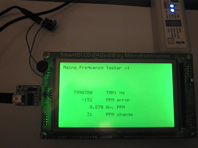
Measuring 50Hz mains frequency 4th June 2011
After calibrating my SmartGLCD against the GPS, I set up this simple
rig to test the accuracy and stability of the Australian 50Hz mains frequency.
I know my clocks that run synced to mains frequency here are very accurate
and have heard that in general the Australian mains freq is quite accurate, so
maybe this 50Hz freq could be used for some calibration use?
I programmed my SmargtGLCD module to do the tests, as it has a larger
display and much more RAM (over 3k) than my EasyPIC6 setup seen above.
It measures the period of 50 mains cycles (1 mains second) with a
resolution of 125nS. So the one second period should read about
8 million ticks, and as TMR1 ticks are in Hz that is 8MHz.
Hardware;
Mains freq was supplied after a transformer as a nice smooth 12v AC.
This goes through a 12k resistor and is limited to 5.6v and -0.6v
by the PIC port internal diode. A 0.1uF cap was placed from the port
pin to ground to kill any noise but is probably not needed as the
transformer output is very smooth. The small PCB shown is a "USB-Usart"
so it can send data back to be logged on the PC.

Procedure;
1. Show exact period for every 50 mains cycles (every "mains second")
2. Show PPM (Parts Per Million) error of the mains second against a perfect second
3. Average the PPM error in a filter to see trends
4. Show change in PPM error from every second to the next
Overall it worked pretty well. Mains freq error was typically less than
500 PPM in any one second, and had definite "trends" of up for a few minutes,
down for a few minutes etc.
Mains freq PPM error charted over 17 minutes.
Above shows one lot of testing. This test shows a particularly large
bump up to 2000 PPM, where the mains freq was slow (as xtal read high)
for about 2.5 minutes! Over this time the average error was almost
1000 PPM which meant the mains got "out of sync" by about one mains
cycle every 20 seconds compared to the xtal!
This would make it interesting syncing a clock to the mains or
"disciplining" a xtal clock to the mains freq. Obviously these
short term mains freq errors are corrected later on as mains-synced
clocks keep excellent time...

Change in PPM error each second.
Above shows another test of about 15 minutes total. It charts the
change in mains freq (in PPM) from one second to the next.
This looks a bit better for making a "mains synced" clock! Each mains
second never seems to get longer or shorter by more than about 150 PPM
at a time.

Change in PPM error averaged over 5 seconds.
Above also shows the change per second, this time averaged over 5 second periods.
Total chart time was about 17 minutes. It shows that the average change
is usually less than 50 PPM per second, over any 5 second period.
This is now looking like something a clock can synchronise to.
It seems to show a definite "correction frequency" where the mains
freq corrects itself about 4 times a minute.
PLL mains-synchronised 1 second clock 4th June 2011
First, why don't we just divide the mains frequency by 50 (or 60) to get a
1 second synchronised clock? It is an obvious question, and is one
method used in cheap commercial alarm clocks. But it relies on the mains
always being without fault. If a mains cycle has a power glitch, brownout,
short term loss of power etc then the 1 second period will be faulty and
even worse, there will be no correction later.
The goal of this mains-synced 1 second clock generator is to
generate every 1 second period with very little short term error, and
to continue to generate the 1 second period even when mains fails and
re-sync as soon as the mains comes good. It will also exactly track
the long term accuracy of the mains freq by staying in sync with the mains.
Design goals;
* A pulse is always generated every second
* Never has more than 100 PPM change from any second to the next
* Will remain mains synced
* Will tolerate a high percentage of faulty mains cycles
* Will continue normal output even with total loss of mains freq
* Will re-sync after longer periods of mains loss
* Will maintain full sync with short periods of mains loss (a few seconds)
PLL procedure;
1. At startup; Measure 1 second mains period and sync to it
2. Each second; Generate a 1 second pulse, then check for mains sync
3. If mains edge was early; subtract 100 PPM from next generated pulse
4. Else if mains edge was late; add 100 PPM to next generated pulse
5. In the event of total mains failure, keep the second pulse at the same length
6. Fix max error always within +/-3000 PPM per second
While good mains pulses exist, the generated 1 second period will always be
made shorter or longer by exactly 100 PPM (100uS) every second, to keep it phase
locked to the edge of the 50th (or 60th) mains pulse. But unlike most
phase locked loops it has "smart" factors, because there is a limit to the
total amout of error allowed in the generated second, there is a fixed
amount of change per second and there is a system for coping with total
loss of input pulses.

After the initial startup and sync to the mains, the PIC only ever
checks the mains input at one instant point for each 1 second.
This means that the mains freq can have any fault for the rest of
the second, provided that one point is ok. Also, even if that point
in the mains is faulty it is always corrected later which allows
multiple faulty (or missing) seconds of mains with very little effect
on the overall sync as it just re-syncs when the fault period
has passed. It will tolerate quite long periods of mains loss, maybe
as long as 60 seconds, without losing the original phase sync (although
this will depend on how much the mains freq changes over that time).
Note 1; The PIC generated second should always be limited between 1003000uS
and 997000uS (which is +/-3000 PPM).
Note 2; In the event of mains failure during any second, the period of the next
generated second should be the same as the current second. In the event of prolonged
mains failure it might be best to fix seconds at 1000000 xtal uS each (so it acts
as a typical xtal based clock during prolonged mains failure).
Note 3; The PIC should have a xtal tuned somewhere within a few hundred
PPM of an accurate second (that means pretty much any xtal type is ok
including ceramic resonators).
PCL mains-synchronised 1 second clock 4th June 2011
The PLL system above will track the mains freq exactly over long periods
of time (provided there are only small faults to the mains). However it
suffers from the fault that it tracks the mains too well! In any minute
where the mains is running 1000 PPM fast the clocks will also run 1000 PPM fast.
ie; It duplicates the short term freq error of the mains freq.
This PCL system below (Pulse Counting Loop) was the first idea that
"sprung to mind" for keeping the PIC-generated second much more stable
but still ensuring that over any long period of time the PIC generates
the same "amount of time" as the mains frequency.
Design goals;
* A pulse is always generated every second
* That pulse is always very accurate, within 50 PPM of a perfect second
* Over any long time it always tracks the average mains frequency
PCL procedure;
1. At startup; Sync to incoming 50Hz mains pulses
2. Each second; The PIC generates 50 pulses, at either 20001uS or 19999uS period (+/-50 PPM)
3. Constantly count all mains pulses and PIC generated pulses
4. If mains count < PIC count, make the next 50 PIC pulses at 20001uS
5. Else if mains count > PIC count, make the next 50 PIC pulses at 19999uS

This PCL system has a nice advantage that the 2 pulsetrains do not need to
be in phase, and at any point in time they can be out of phase by many full cycles!
However it never loses count of the error between the total number of pulses
generated by mains and the total generated by the PIC.
The result is that the PIC produces every second always within +/- 50 PPM accuracy
of a perfect second, and the mains can have 2000 PPM (or much more!) in error
per second at any time, but over any long time both mains and PIC will always
produce the same total amount of pulses!
Note 1; As it needs to have an accurate count of the 50Hz mains pulses
at all times, a simple PLL system should be used to "capture" the incoming
50Hz pulses which will still produce an accurate count even when damaged or
missing pulses occur. (The simple "Window PLL" system below can be used for
counting mains pulses.)
Note 2; As a method for counting both pulse trains up to "infinity"
I would use two 16bit unsigned variables that can count up to 65535, and
when either count gets >65000 then subtract 1000 from BOTH counts. This will
always retain all the count error, and allow recording an instantaneous
count error up to 64000 counts which is ridiculously high as the count
error would be expected to always be much less than 100 and usually
very near to zero.
Note 3; The PIC needs an accurate xtal as it generates each second
+/-50 PPM the xtal needs to be much better than that. Either the xtal osc
can be adjusted to <5 PPM error or simply calibrated to <5 PPM error in
software. If there is no test equipment available to calibrate the xtal
the PCL system can use a larger per-second correction (say +/-200 PPM) and
rely on the xtal being less than 150 PPM error itself without being calibrated
(most PIC+xtal+22uF caps do better than 60 PPM or so).
Crude "Window PLL" for syncing to mains pulses 4th June 2011
This is a system I have used for some years to get a simple phase lock
on mains frequency pulses. It uses a "window" of a fixed width in uS,
and the next pulse must sync within that window either at the start, during
or end of that window.
This is an extremely simple and reliable way to get a phase lock on the
input frequency and will be completely immune to noise or faults that occur
during 19990 of each 20000uS (99.95% of the time).

Window PLL procedure;
1. On startup; Sync to mains pulse / edge
2. For each pulse; Wait a fixed time of 19990uS
3. Then allocate a 20uS window, re-sync must occur within this window;
4. Sync on mains edge going high /
5. Else if did not go high / then sync to end of window
The numbers as shown allow a +/-10uS correction every mains pulse or
about 500uS correction every second (+/-500 PPM per second). This is
plenty of correction to stay in tight sync with the mains frequency.
If there is a complete loss of mains signal the phase error will
increase at a fixed rate of 10uS per 20000uS mains cycle so it will
tolerate up to 800 or so missed mains cycles (16 seconds) and still
re-sync to the same phase when the mains comes good.
It is not as good as the 2 systems above as it can have up to 500 PPM
change over any one second, and the length of any second it generates
is never predictable from second to second. But it will track the mains
frequency more quickly and is very reliable and easy to implement.
It is ideal as an input system to count or measure mains pulses for use
in a more sophisticated sync system (see above).
Note 1; The numbers shown above are ok for use with a xtal.
This Window PLL can be used with PICs that have poor timing (like
internal 4MHz RC osc) but you should allow a much larger window size.
The window size should be at least 4 times the PIC osc accuracy, so
with a internal osc that is +/- 1% accurate you should have a window
at least 4% in width. ie; 20000uS * 4% = 800uS window width and
19600uS fixed period.
Note 2; Obviously, you could make the window occur every 50
pulses so there is one window every second and it will sync to one
mains pulse every second. Again you should make the window large
enough to allow for average mains drift of +/-100 PPM per second,
and be a few times larger than the PIC osc error. With a PIC and
uncalibrated xtal a window width of 500uS and fixed time of 999750uS
is about right. I would not suggest a 1-second sync when the PIC has
a poor oscillator like the internal RC osc!
Mains frequency for calibrating test equipment? 4th June 2011
It doesn't look good. Although the mains clocks keep good time there
is too much short term error for calbration purposes. Not only are
there the short term mains freq errors every minute but longer larger
corrections every now and then, and the daily cyclic corrections
from periods of high power use; ie daytime, dinnertime then low power
use in the nighttime.
I programmed the SmartGLCD to do VERY long term averaging over many
hours but there was still cyclic movement of a couple of PPM. To get
a decent average would require at least one full 24 hour period to
include the daily cyclic corrections, and possibly averaging of more
than one day to try to calibrate the xtal to as good as 1 PPM.
As a comparison, the GPS output (see page top) calibrated the xtal to
0.1 PPM (or 1Hz on a 10Mhz xtal) in the first second of testing!
Making a "mains disciplined" clock?
A "mains disciplined" clock would be to run the PIC xtal at a steady frequency
that was determined by the long term average of the mains frequency, with only
the smallest adjustments (0.1 PPM?) at rare intervals to trim the PIC xtal
to a perfect second.
This looks unreasonable as the mains frequency would need to be averaged over
a 24 hour period or more to get an accurate time reference, so the integral
time constant is stupidly slow. Even hour to hour the xtal will change freq
slightly because of room temperature changes, and this change is much faster
than the time needed to accurately sample the mains frequency. I think the
idea of mains disciplining is fundamentally broken but of course the
mains-synced systems above will work very well for clock use and are simple
to implement.
Particularly the PCL system which will give an excellent level of performance
for mains-synced household clocks.
Make decimal frequencies in 0.00001 Hz resolution! 15th Sept 2012
This PIC16F or PIC18F source code uses any handy xtal, and generates a very exact frequency that is adjustable in real Hz steps (actually in 0.00001 Hz steps).
The lowest freq possible is one unit, or 0.00001 Hz. (Please be warned, at this freq it will take 30 hours to make a single pulse!)
The highest freq possible is;
TMR2 freq / 200
For example; with a 4MHz xtal HS mode TMR2 is 1Mhz so the max freq is 1Mhz / 200 = 5000.00000 Hz. With a 10MHz xtal in HSPLL mode (40MHz) TMR2 is 10Mhz so the max freq would be 50000.00000 Hz.
(Code also supplied for 0.0001 Hz to 50000.0000 Hz)
Theory;
This uses a decimal recurring TMR2 period of 100 ticks, as a DDS addition into an accumulator. This is combined with a decimal setpoint used to trigger the toggling of the output pin. The decimal setpoint is implemented using a bresenham subtraction which keeps any remainder data so it does not need to be a direct multiple of the 100 tick TMR2 period.
Because of the decimal TMR2 period, the freq adjustment is in exact Hz in 0.00001 Hz steps, set by one simple user variable; freqHz.
Because of the bresenham subtraction used as the toggle setpoint, any xtal frequency can be used and will not affect the operation of the decimal system. Like the other bresenham systems on my web page;
Zero-error PIC timing systems
this "bresenham" event that makes the output frequency keeps any remainder for the next cycle, to give zero error over time. So the xtal frequency does not need to have any relationship to the decimal Hz output frequency. So you can use a 4Mhz xtal, 6MHz xtal, or even a junkbox TV colour xtal like 8.867238MHz, and still get exact 0.00001 Hz steps in output resolution!
Simple example of how it works;
Assuming a 4Mhz xtal so TMR2 freq is 1MHz (1 million ticks per second).
Every 100 ticks (100uS) a TMR2 interrupt occurs. If we add 100 to the accumulator, when the accumulator is >= 1 million ticks we generate an event.
As there are 1 million ticks per second (set by the xtal) that >= 1 million event will occur exactly once per second, so the value we added (100) represents exactly 1.00 Hz generated.
With the same setup if we added 200 the event would occur exactly twice as fast; at exactly 2Hz. So adding 200 = 2.00 Hz. Likewise adding 2000 = 20.00 Hz, and adding 23477 = 234.77 Hz. This is basically a "standard DDS" system however it has been optimised for decimal Hz by using a decimal TMR2 period (which makes an interrupt every 100 timer ticks).
Generating a squarewave;
To make a 1 Hz squarewave output with an average duty cycle of 50:50 means we need to make events at 2Hz, and on every event TOGGLE the output bit. So to generate 1 Hz output we still add 100, but make the event happen twice as often; at 500000 ticks (half the TMR2 freq).
So;
each TMR2 interrupt we add 100
toggle output if accum >= 500000 (toggle at 2Hz, makes 1Hz freq)
Increasing resolution;
Now we have a system to make squarewave frequencies in exact decimal 0.01 Hz steps. We can increase the freq resolution in decimal by multiplying all the factors by 10 or 100 etc.
The limiting point in resolution is caused by the PIC using 32bit unsigned long variables, which will crash if they exceed the max value of 4.29 billion. We have to allow for the highest expected TMR2 freq which is 10MHz (10MHz xtal HSPLL mode);
0.01 Hz resolution; add 100, event at (10Mil /2) 5 million
0.001 Hz resolution; add 1000, event at 50 million
0.0001 Hz resolution; add 10000, event at 500 million
0.00001 Hz resolution; add 100000, event at 5 billion (crash)
So with all PIC 16F and 18F xtal setups it should be safe at 0.0001 Hz resolution, which is pretty good!
Note! With a TMR2 freq of 4MHz or less you could run the top range at 0.00001 Hz resolution! I have made two projects, the LF project is in 0.00001 Hz resolution and is limited to max freq of 20kHz and PIC osc of 16MHz. The HF project is in 0.0001 Hz resolution and good for any PIC osc including 40MHz HSPLL and good for 50kHz max freq.
Jitter;
The system is based on the interrupt period which is 100 TMR2 ticks. This means that any point where the output pin toggles will be in sync with one of these TMR2 interrupts. This gives a limitation to the maximum frequency (which is TMR2 freq / 200), and also produces a significant amount of jitter (phase error) when generating higher frequencies.
The worst case jitter on any toggle transition will be 100 TMR2 ticks. At low frequencies this is generally insignificant;
Example TMR2 8MHz, max jitter = 100 / 8MHz = 12.5uS, so;
Freq 100Hz max jitter is 0.125% of the total period.
Freq 1000Hz max jitter is 1.25% of the total period.
Freq 10000Hz max jitter is 12.5% of the total period.
Freq 49999Hz (worst case) max jitter is about 50% of total period.
It's important to realise the frequency will still be exact, so if set to 123.45678 Hz that frequency will still be exact in average (measured over any significant amount of time) just that any individual toggle edge may have a jitter error of 12.5uS.
This project was optimised to give extremely fine adjustment resolution, in actual decimal 0.00001 Hz steps, from any xtal value. If the toggle edge jitter is not acceptable then there are other systems that will produce a zero-jitter frequency, including the ZEZJ (Zero Error Zero Jitter) system on my web page;
Zero-Error Zero-Jitter timing system
however with a zero-jitter system it is not possible to produce the extremely fine resolution in decimal increments that this project has (or use any xtal value!), as zero-jitter is limited to perfect divisors of the timer frequency.
Please don't be scared off by the theory above!
The freq generating code is extremely easy to use and can easily be added into your own PIC projects. There is just a small simple TMR2 interrupt, and a simple variable you set to select any frequency. Then the frequency is generated automatically by the interrupt!
There are two simple PIC 16F628A projects below, with MikroC source code and "how_it_works" text file.
Download LF project (0.00001Hz to 20KHz) on PIC 16F628A DecimalFreqLF.zip 7kb
Download HF project (0.0001Hz to 50KHz) on PIC 16F628A DecimalFreqHF.zip 7kb
- end -
[Back to Home Page]