
The range adjustment is all automatic, all you need to do is adjust the frequency UP/DOWN.
Remember there are 2 PIC pins, each has a complimentary sine so if you make 2 RC filters you can have 2 sines in push-pull form (say for an inverter).
A final feature I added was a hard coded 1MHz digital output. If you ground the PIC input pin RB5 during startup, the PIC will output exactly 1MHz 50% duty cycle squarewave from pin RB3. This allows you to calibrate the PIC's 10MHz xtal (if you have a xtal trim cap) by attaching a freq meter to output pin RB3. Once in 1MHz cal mode you need to turn the power off to exit cal mode.
Xtal-stable accuracy
The internal frequency control (that you control) is set in actual Hz, so button presses control the freq in Hz. For this reason the buttons will "lock" to actual Hz settings like 1000 Hz or 1200 Hz etc.
Once you set the frequency by the buttons the internal math automatically converts your desired Hz setting to the nearest DDS accumulator value to produce a sinewave of that exact Hz. The math routines I used are pretty good and the limiting factor is the precision of the type-double variables and the internal 32bit precision of the DDS accumulator. Which are both quite good.
Once you set the Hz it will lock and the sine will be very accurate and stable at that selected Hz (as stable as the xtal), and generally the DDS frequency will be accurate within about 5 to 50 PPM (Parts Per Million) which is generally better than most xtals.
Sine quality
It is actually pretty good! At very low frequencies <150Hz there is some slight evidence of vertical stepping, as the sine table used in the math only has a vertical resolution of 95 units. This is mainly a filter issue, if you need superb low freq sines then you need to patch in some more RC filter integration, as the filter values I chose just make an OK all-round filter.
100Hz 5v p/p Note that some of the vertical stepping above is due to the 'scope screen pixel resolution and 'scope ADC noise, but the 100Hz trace does show some evidence of vertical stepping at the peaks.
Below are more screendump sine results for my crude RC (RLC) filter values, as seen in the schematic above. (Actually my inductor was a bit less than 470uH, it was about 360uH.) The sine frequency (as measured by the 'scope) is shown at the bottom of each screen.
The 'scope screen is "pixely" and with a tiny bit of ADC noise makes the sines below look scratchy, but the actual sine waveforms are actually very smooth and nice (as checked on my trusty 1970's BWD analog 'scope). Digital 'scopes have good and bad points. :) :(


You can see that due to my filter choice the sinewave is reduced a bit at higher frequencies, down to 4.5v p/p at 10kHz and under 3v p/p at 20kHz. This is deliberate, it allowed a good tradeoff of filtering from such a cheap simple "junkbox parts" filter.
Even at 20kHz 3v there is stil plenty enough amplitude to use a 10k pot on the output to control the audio level out (which generally needs to be around 1.5v to 2v p/p, to supply an audio "line in" jack).
Second harmonic compensation
The sine table I made has 256 horizontal table values, and a vertical resolution of 95 units. The sine was also properly "compensated" for 2nd harmonic issues that occur when using PWM to make a sine. Please see my earlier project for more details; 1kHz high-accuracy PIC sine generator.
The 2nd harmonic content of these DDS sines is extremely low, essentially no harmonic content in the filter's "sweet zone" from about 1500Hz to 3500Hz. At low frequencies there is some 2nd harmonic due to the vertical errors caused by my sine table vertical resolution, and at high frequencies of course from the horizontal errors caused by trying to reproduce 20kHz from 20 sine table entries (20kHz from a 400kHz DDS).
Above in the spectrum analyser you can see with a 1kHz sine, the 2nd harmonic (which is 2kHz) is barely above the noise floor. Cursors show the 2nd harmonic is 48.8dB down compared to the main sine. And as I said above with sines between 1500 to 3500Hz the 2nd harmonic is gone, totally lost in the noise floor (see below at 2k).
At 5kHz the 2nd harmonic is about 40dB down and by 20kHz it is only 28.4dB down.
These are all filter issues, with a filter optimised for a narrow, specific range of sine frequencies the sine quality would be very good!
Note! At all sine output frequencies I could not find any amount of the 400kHz PWM frequency in the spectrum analyser.
Frequency stability
Frequency stability of the sine is superb. A fixed numerical value is added into the 32bit DDS accumulator at a fixed DDS period (every 25 PIC instructions ie every 2.5uS) so any resulting sine frequency is VERY stable, and the sine freq stability will be about as good as the xtal stability.
Clever DDS stuff
The 32bit DDS (Direct Digital Synthesis) accumulator I coded is just a standard DDS system.
I did however do a couple of clever coding tricks to fit the entire DDS process into 25 PIC instructions, no easy task considering the process must include the 32bit math, the sine table lookup and messy PIC loading of the 8bit PWM value and the 2 separate PWM LSB bits in CCP1CON (PICs are a mongrel for doing it that messy way!). The thing that made it really tricky was the decoding of the 3 PORTB buttons that has to be done during the DDS process with minimum interference to the process (so you can listen to the sine while it is being adjusted).
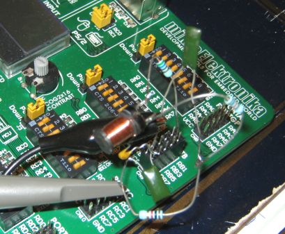
Building it
I didn't bother making one on a PCB, but this has been fully tested on my EasyPIC6 development board. As there is not much more than a PIC and a handful of discretes you should be able to make it quite easily and have a very nice stable good quality audio sine generator.
Improvements will mainly be to the filter values. My filter does the job fine for the whole frequency range but if you want to take a bit extra effort than an adjustable filter (possibly an opamp based low-pass filter?) would be of significant benefit and give you really nice sine output especially at the low and high ends of the freq range.
Another important improvement would be to put a trimmer cap on the xtal instead of the 22pF ceramic cap. Then use a good freq meter to tune the xtal to as close to 10MHz as you can get it. My xtal was previously tested and known to have about 45 PPM (slow) error. This is not much error but is enough to make the 20000Hz sine output at 19999 Hz (see screendumps above). If you get your xtal running at exactly 10MHz this project will give you a very respectable sine freq accuracy. :)
The HEX file is below, for programming into a cheap 18pin PIC 18F1320
Download the HEX file; SineDDS.zip 4kb (Note! this firmware now includes 4 waveforms)
Merry Christmas! :)
NEW! Version 2 HEX file has 4 waveforms!
New for 30th Dec 2011;
The project now has 4 wavetables! If nothing is connected to PIC pins RB7 and RB6 the PIC will default to a sine wave (same functionality as v1 firmware).
1. Sine wave = RB7 HI, RB6 HI
2. Square wave = RB7 HI, RB6 LO
3. Sawtooth wave = RB7 LO, RB6 HI
4. Triangle wave = RB7 LO, RB6 LO
The PIC pins RB7 and RB6 have internal pullups, all you need are two switches, a switch from each pin to ground. Two switches sets any of the 4 possible waveforms. And if you connect no switches it will still default to a sinewave.
Filter changes! The square wave is best with no filter at all, so just take the digital square wave from PIC pin RB3 (before the filter). For the sawtooth and triangle waves the best filter depends on the frequency, and the filter values shown at page top are ok for lower frequencies. To get good sawtooth or triangle waves at higher frequencies you will need to reduce the filter values (use smaller caps and/or smaller resistors and remove the inductor).
Also like the original sine wave, for all 4 waveforms an opposite (complimentary) wave is available at pin RB2.
- end -
[Back to Home Page]