[Back to Home Page]

www.RomanBlack.com

PIC with 2 clock speeds!
The PIC can change its own clock between fast and slow for energy savings
Roman Black - orig Nov 2000 - updated Aug 2006


What is it?

This is a system where a PIC microcontroller can switch between 2 clock speeds by setting one of its digital outputs. This is NOT my idea, just my implementation of a concept that was being discussed in Nov 2000.

This is a useful feature that enables the PIC to run at a very slow speed for energy saving, then occasionally speed itself up to perform specific tasks. Normally the PIC clock is thought of as the controlling force that determines the speed of the PIC, but this implementation allows the PIC to control its own speed which may be useful for specific applications. (Note also that an external device could select the PIC's clock speed).

I designed this system in Nov 2000 to work with any PIC, even the small cheap ones. Recently larger PIC's with the ability to switch between 2 crystal types are becoming more popular. My system here is crude and only uses the RC oscillator which will not give crystal-accurate timing.


How it works


This is a PIC RC clock. The value of R (Rext) and C (Cext) determine the PIC clock frequency.

RC oscillator operation is very simple;
  • C charges from +5v with current supplied by R
  • When C reaches about 3.5v, Osc1 schmitt buffer output goes HIGH
  • The discharge fet turns ON
  • C discharges through the fet to ground
  • When C lowers to about 1.5v, Osc1 buffer goes LOW
  • The discharge fet turns OFF
  • (cycle then repeats)

    If we increase the capacitance of C it takes longer to charge and the clock is slower.
    If we increase the resistance of R it takes longer to charge and the clock is slower.
    
         +5v -------*-----------------------------*---------------
                    |                             |
                    |                             |
              560k  |           D           ,--------------,
                    R1                      |              |
                    |   ,------|<-----------| Output1      |
                    |   |                   |              |
                    |   R2                  |              |
                    |   |  5k6              |         PIC  |
                    |   |                   |              |
                    *---*-------------------| Osc1         |
                    |                       |              |
                    |                       |              |
                    C1                      |              |
              22pF  |                       '--------------'
                    |                             |
                    |                             |
                    |                             |
         Gnd -------*-----------------------------*---------------
    
    
    Shown above is the simplest way for a PIC to change its own RC clock speed;
  • When the pic output pin Output1 is LOW, R2 is disconnected and the PIC clock is determined by R1 and C1 in the normal fashion.
  • When Output1 is HIGH, charging occurs through both resistors and the PIC clock is much faster.

    The SLOW speed is set by R1.

    The FAST speed is set by R1 in parallel with R2, but if we assume that R1 is a very high value and R2 is a low value it is simply easier to say;
    The FAST speed is set by R2.

    Some would argue that the diode D can be removed and the pic output pin changed to high impedance (input) to set the PIC to SLOW mode. However I am not convinced that it is wise to have a PIC I/O pin oscillating through a triangular waveshape at its own clock frequency! It seems better to spend a couple of cents on a 1N4148 glass diode.

    The parts values shown above should give a fast clock of about 4MHz, and a slow clock about 100 times slower; about 40kHz. With an R1 value of 5.6 megohms clock speed will be 1000x slower (a few kHz) and a small PIC like a 12c508 will only require <20uA or so and can still perform useful tasks and keep count of a long term timer.

    The PIC can switch between clock speeds in LESS time than one instruction, and speed itself up to perform just a handful of instructions with no real penalty in power usage and no oscillator start up time. (The RC osc is already running and there is no sleep mode to exit).


    Is it useful for anything?

    It is not the type of circuit you would use every day, but it has some value for long period datalogging on low power. I have noticed that many cheap SMD resistors and capacitors now are rated at 1% tolerance and because they are laser trimmed the values often measure at much better than 1%. RC oscillators are impervious to shock and vibration and are great for travelling devices. Temperature sensitivity is not too bad and can always be compensated in software, especially if it is a temperature logger and the cost of a temperature sensor is already included.

    There are many datalogging applications that would benefit from low power use and low cost (no crystal cost) and a period accuracy of a few percent is quite acceptable.

    Something like a tiny solar powered solar-survey logger that takes a measurement every 10 minutes. Or maybe a solar logger that takes a reading at solar noon every day and needs to track a decent 24 hour period, occasionally resetting its "noon" time based on dawn and dusk times. Getting a decent 24 hour period using sleep mode and the watchdog timer is very difficult, but a constantly running very-low speed PIC can do that with ease!

    Maybe a smart remote control that stays awake all day at a very low RC clock speed and knows what time of day it is, resetting its own hour clock once or twice a day as one of the PICs high-speed infrared tasks. There is no crystal cost and a clock speed lower than any crystal is possible giving lower power consumption.

    Its usefulness is based on these points;
  • It can stay awake and timing at very low power consumption
  • (provided clock accuracy of a couple of percent is acceptable)
  • It can speed itself up to full oscillator speed instantly for comms and tasks
  • If you need different and specific clock speeds

    It would also be possible to have more than one control pin, each with a diode and tuned resistor. The PIC could select between many clock speeds instantly which may have uses for communicating at many different comms speeds with the same code. Maybe a sound synth with 12 different clock speeds, so the same code could generate complex waveforms and harmonics and still produce the 12 notes needed to make music.


    Issues with widely different clock speeds

    To achieve widely different clock speeds like the 1000x example shown above you need a high value resistor for R1 which is not recommended. Although perfectly safe and it won't damage the PIC there can be issues with oscillator speed variance.

    Microchip's recommended maximum for Rext is 100k ohm, stating in their datasheets that for very high Rext values like 1 megohm the oscillator becomes susceptible to pin leakage, humidity and EM noise.

    Humidity can be reduced by a blob of epoxy over the circuit and EM noise can be reduced by some foil sheilding. The variation from PIC pin internal leakage seems to be small. I did tests of a worst case "exposed" circuit with a 1 megohm resistor, no moisture or EM sheilding and LONG wires connecting the components (actually using through-hole components in a plug-in protoboard).

    Results were fairly encouraging, different new PICs from the same manufacturing batch all oscillated within 2% of each other, and stray capacitance from holding my hand extremely close to the circuit had very little effect. I would be reasonably confident using >1 megohm resistors in some apps and still expect timing within a few percent.

    An alternative that may be useful was one I designed in this original text in Nov 2000, a system that allows 2 different caps as well as different resistors. Basically this gives 2 entirely different RC networks! I tested a prototype that happily switched itself between 1MHz and 29Hz(!!) and with resistors still in-spec. The circuit and parts values are shown below.
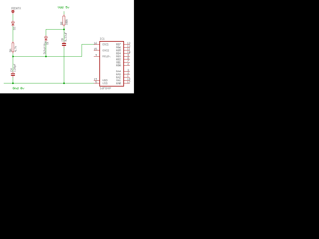


    Operation is as follows;
  • PointX is the speed control, can be controlled by a PIC output pin
  • When PointX is LOW, speed is SLOW
  • (RA is disabled and timing is by RB and both caps)
  • When PointX is HIGH, speed is HIGH
  • (RB and CB are disabled, and RA and CA determine the timing)

    The circuit works because RB is much larger than RA and when in HIGH speed mode CB is discharged every cycle like CA, but CB does not get time to charge. It works very effectively provided D1 is a schottky diode or other fast diode with a low Vf (<0.3v). The schottky I used for D1 was a 1N5819 but there are much smaller and cheaper ones available that will do the same job. D2 does not need to be a schottky and a cheap common 1N4148 will work.

    When I did that test in Nov 2000 the old PIC 16F84 never got much below 60uA even with the very low clock speeds. The newer PICs (especially the small simple PICs) are more efficient with less quiescent current and are capable of very low running currents at low clock speeds.

    The question remains whether a VERY low running speed like 29Hz is useful for anything, but at least this dual RC system does enable tuning of two desired frequencies that can be radically different.

    - end -

    [Back to Home Page]