[Back to Home Page]
www.RomanBlack.com
The NO-parts LED driver!
Driving a 12 digit display with no parts, just a PIC
- 06 June 2009

What is it?
I got some of these great little 12 digit 7 segment LED displays from
Aussie surplus reseller;
Oatley Electronics.
Check out their "bargain corner" to check the current price, I was told
they have good quantities remaining and they WILL sell international.
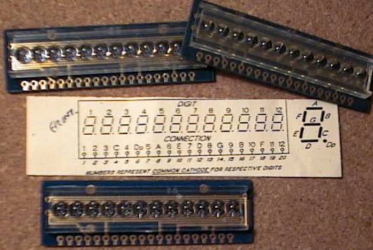
When I found out they were digit-cathode (ie 12 cathodes, one for
each digit) I looked at options for driving them, and the options were
dismal; 2 cathode driver chips (ULN2003 etc) and 2 cathode register
chips, and 8 resistors for the 8 segments (7 seg + decimal point).
Hmm... 4 chips, 8 resistors, and HEAPS of nasty work wiring it all up.
So I thought, "Wouldn't it be nice if there was just ONE chip needed
to drive this thing?" and the solution I came up with was even
better... How about using NO CHIPS and NO RESISTORS to drive it? :)
How does it work?
I had seen LED multiplexing done with no resistors before, this was only
really done back in the dark ages and does not seem used now.
But I don't like using PIC port pins outside their maximum
current specs so it needed some testing with this display to make sure
the display would be;
Bright enough
Not cause damage to the PIC
Not have segments of different brightness
The schematic is simple; the 8 segments (includes decimal point) connect
direct to 8 PIC pins on PORTB, the 12 digit cathodes connect to
12 PIC pins on PORTA and PORTC. As you can see below the PIC
just connects directly to the 20 pin connector on the LED display.
It uses SOFTWARE to provide a low duty cycle and control the LED current
for each segment.
The prototype
This was the first one I set up to test brightness etc.

I stuck an old junk PIC 16F873 in a socket and soldered it into some
0.1" veroboard. Then just used hookup wire to connect the 20 PIC
pins to the 20 display pins as shown in the schematic above.
I used a 22uF tantalum cap on the PIC power pins (yellow) and a
16MHz 3-pin resonator (blue). As a final touch I used a 33uF electro
cap on the incoming power pins, and a 1.5 ohm resistor to allow
me to measure the average current the whole device draws.
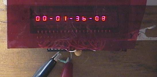
It's ALIVE!!! I set my power supply to 5.0v and stoked it up.
Apparently I got the wires in the right place because it worked!
It looks much better in real life than the photos, these are a very
attractive display and even more so in this day and age when LCD are
so common it's like a treat to see a nice "retro" looking LED.
With 2 layers of red cellophane (from the newsagent)
it has a very nice deep red glow reminiscent of 1970's spy-movie
atom-bomb timers etc! Very sexy.
Is it safe?
With the initial test of the display I made it say '012345678901'
and measured the total current at 51mA which even includes the PIC
operating current!
That is 55 lit segments, at 51mA which is LESS than 1mA per lit
segment. The display is nice and bright, and it was a pleasant
surprise to only need 1mA per segment! This display uses many times
LESS power than a text LCD with a backlight.
Now for the safety. I drove the segments with a duty cycle
of 1:24 so that only 4 segments can ever be lit at one time.
So it multiplexes the top 4 segments, x 12 digits, then the bottom 4
segments for 12 digits again. Multiplexing is at 256uS (using TMR0
interrupt) which runs each LED at 162Hz. There is no deadtime,
so peak (instantaneous) current is 55 segments / 24 multiplex which
is the equivalent of 2.29 segments on all the time, so that is
51mA / 2.29 = 22.3mA per lit segment peak instantaneous current.
22mA per PIC pin is well within safe specs, and the most segments
that can be lit at once is 4, so the max sourced by PORTB in total
is 4x 22mA or 88mA. PORTB is specced at 200mA so that is fine.
The max current sunk into PORTA or PORTC pin is also 88mA, which
is technically above spec but can never be more than 1:12 duty
cycle and must always have the long cool down cycle (11 periods)
after any time it is used. Since the pin pull-down drivers are
NFETs this should be comparable to any pulsed NFET with a low duty
cycle, which is the average of 88mA / 12 or 7.3mA sunk per PIC pin
is the worst case.
After all that technical mumbo-jumbo the result is clear;
It's bright, it uses very little power, and IT WORKS!
Designing a neat PCB
I made a neat little PCB to take a 28pin PIC (surface mount SOIC package)
and connect it to the LED display.
2 PIC pins are available to the user, so this can be a complete clock,
or just a display driver that only needs a serial input! Now I can add a
12 digit display to a project and only need ONE serial pin to drive it.


This was the first test of the PCB, made using toner transfer.
It worked fine. The artwork below is improved slightly
to add 2 jumpers that disconnect the LED display when you are
programming it with ICSP.
You don't really need to drill holes in the PCB either, all the parts
can go on the top which makes construction faster.
Click HERE for PCB artwork! (300 DPI)
Below I have provided 3 applications for this little PCB;
Clock, with hundredths of seconds
999 hour stopwatch, with hundredths of seconds
Serial controlled 12 digit display, numbers AND characters
App1. Clock
This is a clock that shows HH-MM-SS-hh where hh is hundredths of
a second. The 2 inputs to the PCB are for 2 buttons; "set hours" and
"set minutes".
Important! RA0 is to be connected to P20. RC6 and RC7 are the 2 buttons.
(see PCB above)
There are two versions of the clock, one is a 24-hour clock
that displays hours from 00:00 to 23:59 (military style) and the other
clock is a typical 12-hour clock showing hours from 01:00 to 12:59.
The 12-hour clock has an AM/PM indicator in digit0, similar to many
bedroom alarm clocks. If you don't want to show the AM/PM indicator
then don't connect pin1 of the LED display, this turns off digit0.
Here is source code and HEX file for the 24-hour clock; ALL TESTED.
24-hour Clock; source code for MikroC
24-hour Clock; HEX file to load direct into a PIC16F876
Here is source code and HEX file for the 12-hour clock; ALL TESTED.
12-hour Clock; source code for MikroC
12-hour Clock; HEX file to load direct into a PIC16F876
App2. 999 hour stopwatch
This is a stopwatch that counts UP to 999 hours. The display shows
HHH-MM-SS-hh where HHH is 000 to 999 hours, and hh is hundredths of seconds.
One input conencts to a button that resets the stopwatch count.
The other input can go to a button or switch, it pauses the stopwatch.
Important! RA0 is to be connected to P20. RC6 and RC7 are the 2 buttons.
(see PCB above)

I have provided source code in C for MikroC compiler, and HEX file so
you can just load it direct into a PIC. ALL TESTED.
999-hour Stopwatch; source code for MikroC
999-hour Stopwatch; HEX file to load direct into a PIC16F876
App3. Serial 12 digit display
This is a bit more sophisticated. It accepts serial in on one PIC pin
at 19200 baud 8 bits, no parity and 1 stop bit (standard 19200).
You get full control over every segment, so you can display numbers and
text like this;

I wish it was as easy to photograph as it is to send data to.
As I said before the display looks SO much better than the photos.
It accepts three serial commands, each is just 1 byte;
10xx PPPP, move to digit PPPP,
ready to write to that digit
0SSS SSSS, where SSS SSSS is the data for 7 segments,
where 1 lights up that segment. Segments are GFEDCBA.
11xx PPPP, light up a decimal point at digit PPPP,
then move to next digit
After sending segment data, the digit position automatically moves to the
next digit. Digits are numbered 0-11 where the leftmost is 0. After
writing to digit 11 it wraps back to digit 0, so you never need to send
a move command if you are always writing 12 digits (unless you want a
decimal point).
I designed it that way to make it fast and easy to write segment data.
The decimal point must be written AFTER that character.
Important! RA0 is to be connected to P20. RC6 is not used. (see PCB above)
I have provided source code in C for MikroC compiler, and HEX file so
you can just load it direct into a PIC. ALL TESTED.
Serial Display; source code for MikroC
Serial Display; HEX file to load direct into PIC16F876
Future LED projects
I designed the PCB so that the analog input to the PIC (AN0) can
be connected as an input and RC6 used to drive pin20 of the display.
This allows the display to be used as a panel meter, displaying
volts or amps etc or any other analog reading. When I get around to it
I'll make up a panel meter application and put it here.
Final thoughts?
Well all in all this worked pretty good. The segments are attractive and
uniform in brightness apart from the decimal points which are a little
brighter than the other seven segments. This is a characteristic of the
display and not the system used to drive it, and if anything it makes the
decimal point a little easier to see as it is quite close the to C
segment. This is easily "fixable" with just one resistor to pin 6
of the LED anyway.
Using the LED display requires either soldering 20 wires or making
a PCB, which is a bit of a pain. But then using a character LCD involves
wiring a contrast pot and connecting 10 or so wires which is a bit
of a pain too. The LED uses more power than a plain LCD but is still
quite efficient, surprising that it uses 10 times less power than a
LCD with backlight, the type I normally use! Most of the LED display
tests (above) were under 40mA. If power consumption is an issue I tested
the display was still readable even at 1:72 duty cycle (3x less current)
but wasn't great in a bright room.
The LED display viewing angle is a little narrow because of the
built in magnifiers over the digits. Sometimes when close you have
to bob your head a few inches to get a good view of the digits.
Likewise they are small digits, readability is not good if you
are more than 4 foot away from the display.
One area the LED was much better than a LCD was speed. The hundredths
of seconds on the clock and stopwatch are a delight to watch, where
an LCD struggles a bit even with tenths of seconds.
Likewise getting 12 digits from a display that costs about
a buck and can be driven directly from a PIC is pretty cool. Or that
can be driven from just 1 PIC pin as serial data.
But the thing I like the most is that deep red "retro" look...
My new master clock for my home automation is getting one of these
little beauties!
- end -
[Back to Home Page]
