[Back to Home Page]
www.RomanBlack.com
Some projects using the BIGPIC6
RS232 baud timer, RS232 baud converter, RS232 digital storage CRO
- 2nd Jan 2010.
All the BIGPIC6 projects and source code on this page are open-source.
You can use my code for hobby or commercial use, but please mention me.
You can also see my REVIEW of the BIGPIC6 HERE
BIGPIC6 Project 1. Serial baudrate timer
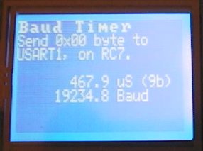
My PC's 19200 baud is really 19234.8 baud (0.18% fast)
What is it?
This project displays the incoming baudrate from another device. The other
device must be connected to USART1 and must send a 0x00 byte. This is useful
for tuning PIC baudrate generator values or anytime you need to see exactly
what baudrate a device is transmitting at.
It times the period for the entire 0x00 byte, which is 9 zero bits (start bit
followed by 8 zero bits). This period is timed very simply by using TMR1
running at 0.1uS resolution.
Then the BP6 displays the total byte period (9 bits) on the GLCD, and
does the math to convert that to actual baud and displays the actual
baud to 0.1 baud resolution. Accuracy is quite good especially at lower
baudrates. Even at high baudrates like 115200 baud the accuracy is still
quite good with a total byte period of 780 counts, a 1 count error is
still less than 0.2%.
Limitations;
A single zero byte (0x00) must be sent, other byte values will cause a wrong reading
Requires;
BIGPIC6 and 18F8520, 40MHz HSPLL
External device to be measured connected to USART1 (RC7)
GLCD
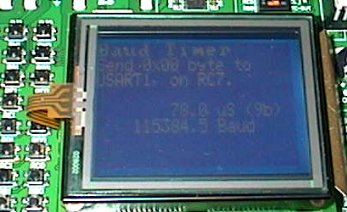
My PC's 115200 baud is really 115384.5 baud (0.16% fast)
Adapting this code...
This does not use the BIGPIC6 USART, it manually times the period at RC7 so this
code could be adapted for use on other PICs. It also does not require
GLCD, it could use a text LCD as the data is displayed in text form.
However most of it's accuracy comes from using TMR1 at 10 million
counts/second. If you use another PIC at 20MHz xtal (TMR1 = 5 mill) then
you would still get pretty good accuracy.
This .ZIP file contains the MikroC v7.0 source code in C,
the project file, and the HEX file.
BaudTimer.zip
BIGPIC6 Project 2. Baudrate converter 1
What is it?
One of the main things my BIGPIC6 will get used for is a support board
for projects being designed on my EasyPIC6 etc. As the BIGPIC6 has dual serial
ports it is ideal to be used for serial generation or analysing.
This project is a baudrate converter. It is fully bi-directional
asynchronous RS232 converter with any 2 baudrates from about 3200 baud up to
about 200000 baud. The higher speed RS232 USART must be connected to USART1,
and the lower speed (or equal speed) USART is connected to USART2.
There is a 1792 byte buffer connected to USART1 RX. Provided the buffer used
"buffer load" (instantaneous difference between bytes in and bytes out) never
exceeds 1792 bytes the project will perform perfect baudrate conversion
between the two USARTS. So in actual use the fast USART1 can receive high
speed packets which will be continually sent out to USART2 at a lower
baudrate. Sending the other direction (from USART2 to USART1) happens
immediately and does not need a buffer.
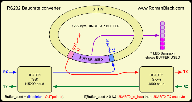
The buffer system is an extremely simple circular buffer with
2 pointers; inpointer and outpointer. Every incoming byte is placed into
inpointer, then inpointer is ++. If outpointer does not equal inpointer there
are bytes in the buffer so provided USART2 is free it sends a byte out
and outpointer is ++. Outpointer constantly tries to catch up to inpointer, as fast
as USART2 can send. The difference, the buffer load or "buffer used" is displayed
in real time on a 7 LED bargraph on PORTB. No protection for buffer overrun
is implemented.
Limitations;
Buffer size is 1792 bytes
The higher of the two baudrates must be on USART1
Lowest baudrate is about 3000 baud because PIC runs at 40MHz HSPLL
Highest baudrate is about 200000 baud because it is drawing bargraph
It requires a 40MHz PIC with two USARTs
You must change the baudrate settings in source code and re-compile
Requires;
BIGPIC6 and 18F8520, 40MHz HSPLL
USART1 and USART2
7 LEDS on PORTB, RB7-RB1
Multi-threading?
This project is one of the first to use my
PIC-thread multi-threading systems.
Each process (like the two USARTs and the bargraph) are operated in their
own "thread" to form a crude but effective multi-tasking system that
handles the bi-directional comms and also displays buffer usage on the
bargraph LEDs.
This .ZIP file contains the MikroC v7.0 source code in C and the HEX file.
BaudrateConvert1.zip
BIGPIC6 Project 3. Baudrate converter with GLCD
What is it?
This is a more sophisticated version of the BaudrateConverter1 above.
This version has a GLCD to show the both USART baudrates, and the
baudrates can be changed up/down on 4 PORTB buttons.
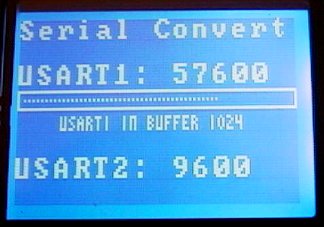
The bargraph shows the USART1 buffer filling up, it has 62 bars and
is updated every 10th of a second.
Baudrates; 3200, 4800, 9600, 19200, 38400, 57600, 96000, 115200.
Limitations;
Buffer size is 1024 bytes
The higher of the two baudrates must be on USART1
Lowest baudrate is 3200 baud because PIC runs at 40MHz HSPLL
Highest baudrate is 115200 baud because it is drawing bargraph
Only 8 specific baudrates are available (see above)
It requires a 40MHz PIC with two USARTs
Requires;
BIGPIC6 and 18F8520, 40MHz HSPLL
GLCD
USART1 and USART2
4 baudrate up/down buttons on RB0-RB3
This is also made using my PIC-thread multi-threading system and is
more complex than the project above because it has additional overhead
of writing the 62-bar bargraph to the GLCD and checking the buttons
that set the baudrate etc. It uses a TMR2 interrupt to generate a
10mS event that operates independent timers that are used to control
thread 3 and thread 4 that display the bargraph and test the buttons.
The bargraph is displayed on the GLCD and has 62 segments, and in keeping
with the multi-thread parallel processing concept the 62 bars are drawn
and erased independently which keeps the main threads fast to allow bidirectional
comms without failures. Basically it is "parallel" because the bargraph
is being drawn at the same time as the USARTs are monitored and transferred.
There is no protection for buffer overrun, and no error display for it.
However there are two error displays; if either USART gets a framing or
overrun error.
Even in its present crude form with 4 buttons and GLCD and only a small
buffer of 1024 bytes this is a useful tool that can go between 2 RS232
devices operating at widely different speeds. I fixed the buffer at 1024
bytes (to make bargraph calcs easy using 1024->64) but the buffer could be
as large as 1900 bytes if you used all the available
RAM on the PIC which has 2k RAM internal.
This .ZIP file contains the MikroC v7.0 source code in C and the HEX file.
BaudrateConvertGLCD.zip
BIGPIC6 Project 4. Serial storage CRO
What is it?
This project turns the BIGPIC6 into a digital storage CRO to display
RS232 serial data. The serial data is manually sampled at high speed
on pin RC7 which is connected to USART1 RS232 connector.
This is my first proper project using the touchpanel which is
attached to the top of the GLCD so you can "touch" the buttons drawn
on the GLCD.
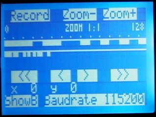
There are 4 recording speeds;
2 Megasample / sec
1 Megasample / sec
500000 sample / sec
100000 sample / sec
Since sampling is done in software and not using the PIC USART it will
record and display data at any baudrate. Number of samples recorded
will always be 8192.
Features;
Recording buffer size is 8192 samples
4 recording speeds (see above)
Serial data to be recorded is connected to USART1
Recording starts automatically with the first "start" bit
2 display waveforms
Baud display pips (12 standard bauds; 300 to 115200)
Fast and slow scroll buttons to scroll display
Requires;
BIGPIC6 and 18F8520, 40MHz HSPLL
GLCD
Touchscreen
USART1 RS232 connector
Using it
Press Record in the top left of the screen.
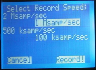
Press the desired sample rate. Then press Record!
Start the serial input, it will start recording automatically
and stop after 8192 samples which will only take a fraction of a second.
Then the serial data will be displayed on the GLCD. There are 2 waveforms,
both show the same data and are indexed to the same position in the recorded data
(their left edge on the screen is the same for both waveforms). The index is
shown in small numbers in BYTES (0 is the start of the recording).
The bottom waveform is always shown at 1/4 zoom (1 Xpixel = 4 samples) and is handy
for navigation. The top wavform is th emain display and can be zoomed at 1/2, 1:1 or 2:1.
The waveforms can be scrolled right or left together, using the arrow buttons.
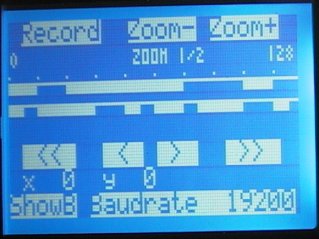
At the bottom of the display there is a ShowB button to turn the
baudrate pips on and off, and a Baudrate button to set the spacing
of the pips. These pips can be seen above the top waveform (and zoom with
it) and are useful when examining the waveform. If the baudrate of the
incoming data is known, just set the Baudrate button accordingly.
The pips are a display feature only (like a grid) and are independent to
the waveform, but even with this limitation they are a very handy feature
as they are calibrated to 1/256th of a pixel.
All in all this porject is a pretty powerful application and a nice useful tool.
Even though it will only record 8192 samples that is still a LOT of RS232
information (especially if you are trying to scroll through it all as it is
64 GLCD screens wide).
I haven't included source code because my menu/button systems are a bit messy
and I used some tricky inline assmbler to get accurate recording at
2 Megasamples / second. It is fully working and a large project (13kbyte
of PIC ROM) and I really can't be bothered tidying up the source for release
on such a big project that already works. The .ZIP file contains the .HEX
file which is all you need to run this on your BIGPIC6, and of course
a GLCD and standard touchpanel which plug straight into the BIGPIC6.
This .ZIP file contains the .HEX file ready for BIGPIC6 and 80 pin 18F8520.
It is tested and working on BIGPIC6 hardware.
CRO_Serial.zip
New! I ported the entire project to work on a EasyPIC6 dev board
and a 40 pin PIC 18F452. It has been tested in hardware. Make sure to turn the
GLCD backlight, touchpanel switches etc on in the EasyPIC6, and also the
dipswitch to connect the RS232 port RX to RC7.
This next .ZIP file contains the .HEX file ready for EasyPIC6 and 18F452.
CRO_Serial_18F452.zip
- end -
[Back to Home Page]


