Evaluation of the changes
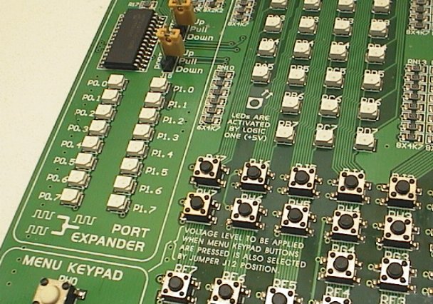
Well this part is a little disappointing. I never got the chance to try the 3 special ports added on the BIGPIC5; the CAN port, RS485 port and DAC port. Unfortunately these have been removed for the BIGPIC6. It's hard to say what was the reason MikroE had for removing these, I guess it might have been an issue of cost, or even lack of demand. The space that the 3 special ports took up on the BIGPIC5 board has been replaced with the 16pin port expander IC.
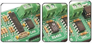
Sadly, these 3 are gone from the BIGPIC6.
I'll agree the port expander is nice, but where the port expander shines on the EasyPIC6 it is less shiny on the BIGPIC6 because big PICs already have 68 IO pins! Personally I would have been happier with the 3 special ports (especially because I don't have them on my BIGPIC4!) but it's undertandable if MikroE have taken these off due to lack of interest or to keep the price down (the BIGPIC6 is actually $30 cheaper than the BIGPIC5 even with the new features).
Also gone from the BIGPIC6 is the PS2 connector, useful for adding a mouse or trackball or keyboard. This connector is basically just a socket and 2 resistors, so really it's not as much a loss as one can be manually connected with a small amount of effort.
On a positive note the port expander adds 16 IO pins, and 16 more LEDs. It's a nice powerful feature, even just for 16 debug display LEDs that don't tie up your application port pins. Likewise the 6 button menu style keypad is a very useful addition, since a typical application for the big PICs is with a GLCD so menu arrow buttons are quite important.
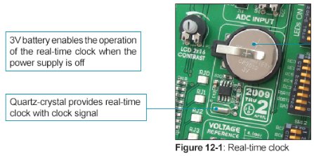
The real time clock IC with 3v backup battery is very useful, and fits nicely with the pro level of applications that can be built with a big 80 pin PIC. I'm quite happy to have this as standard now, it's one of those peripherals that takes a lot of effort to solder up, in fact I bought a MikroE add-on PCB with real time clock some time ago. Check out the little clock picture above with the 2009 date, it looks like the PCB designer had a chuckle putting the design date of the PCB within the clock area of the PCB! It's the many little touches like this that show the enthusiasm and fun of MikroE's brilliant hardware design team. These dev boards are made with a genuine love for what they do.
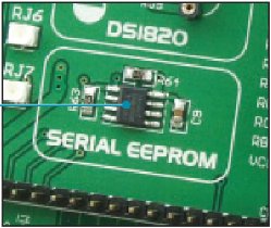
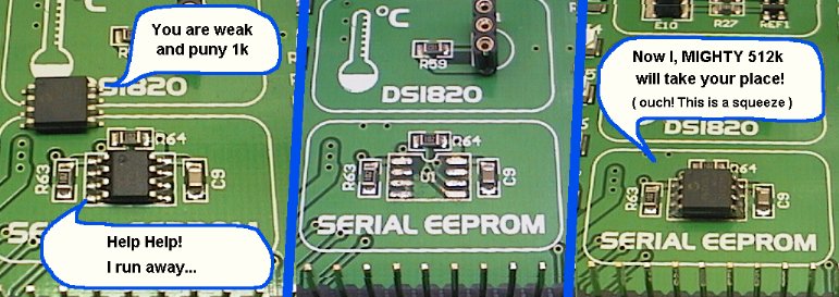
Yay! Finally MikroE have included a I2C serial eeprom as standard! This is a very excellent addition to any development board. It takes almost no PCB space but yet is one of the most useful things you need to add to a PIC application you might be developing. Also good choice on I2C and not SPI, the I2C is (in my opinion) the best standard for this accessory. However I found it quite funny that they used a tiny 1kbit eeprom like a 24AA01 because the PIC itself has 8kbit of internal eeprom! Hopefully MikroE will use a larger eeprom with future production runs!
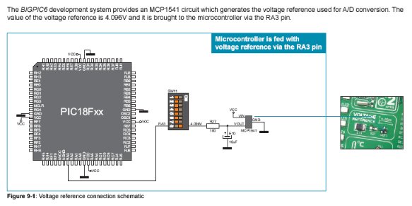
Now in the "very sexy" class (and an efficient use of a little PCB space) is the 4.096v voltage reference. This is very nice, and even though it was included on the BIGPIC5, my BIGPIC4 does not have one and I wish it did. Since the big PICs have 16 ADCs onboard, it makes so much sense to add a precision MCP1541 4.096v reference to make the ADCs accurate for real world voltage measuring. This is already setup to connect to the RA3 pin to act as the +Vref for the ADCs.
Back on a negative note, the SD/MMC card socket is gone. I think having a SD card facility onboard was very useful. One of the typical and valuable applications for a big PIC and LCD/GLCD is datalogging apps and having easy plug-in SD card with up to Gigabytes of storage is practically a necessity. I have SD card socket on my BIGPIC4 so I can still use that but it makes me wonder why MikroE took this useful accessory away. Fortunately MikroE sell lots of cheap plug-in accessories, including a SD/MMC socket.
The nitty-gritty comparison
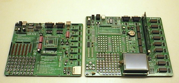
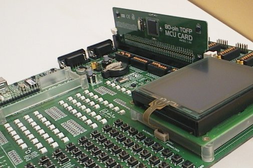
Comparing the BIGPIC6 to my old BIGPIC4 there really is no comparison. Apart from having that nice SD card socket, my BIGPIC4 looks almost embarrassed by its shiny new big brother! (See the picture near the top of the page).
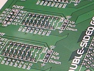
The BIGPIC6 fully supports all the 68 IO pins on 9 PIC ports. It has a LED, a button, a separate pullup resistor switch and an output connector pin for EVERY PIC IO pin! This was a major failing of my BIGPIC4 that it only supported 6 PIC ports for buttons and LEDs, and 7 ports for connectors (not all 9 ports). Don't underestimate the importance of having a button and LED for every pin, or the subtle but valuable benefit of being able to individually select a pullup resistor for every pin. That is most definitely a pro designer feature. You never know what you will be connecting to every pin, and some ports may share analog and digital inputs in your design so being able to add a pullup (or pulldown) to any pin at the flick of a switch is superb! (Although the up/down must be set globally for each port of 8 pins).
The BIGPIC6 easily beats my BIGPIC4 in accessories, again if you look at the side by side picture up top you can see just how much better the BIGPIC6 is.
However if you put it up against the BIGPIC5 the BIGPIC6 still wins, but at a cost. The BIGPIC5 was already a massive step ahead of the BIGPIC4, with full IO pin support and many new additional accessories. The BIGPIC6 has suffered with the loss of the CAN, RS485 and DAC ports. But the BIGPIC6 bounces back and beats it in attractiveness, those VERY visible LEDs AND it beats the BIGPIC5 in price being a full $30 cheaper! It also beats the BIGPIC5 in pro features like the pullup switches, I2C eeprom, menu keypad, and in that other BIG change...
That other BIG change
"Huh? What on earth were they thinking?" I have to admit that was the first thing that went through my mind when I first saw the new PIC adapter board.
I was even a bit annoyed! After all I have an investment in the old square adapter boards used with my BIGPIC4, with 18F8520 and 18F8720 on them and some blank adapter PCBs still waiting to be used.
But I know from experience that people often criticise my actions when they don't know why I did something unusual. It's a "knee jerk" reaction when you have only seen part of the big picture. So knowing that MikroE have some really smart hardware designers and they must have put a lot of thought into this change it's worth taking a second look at the new adapter and really weigh up the pros and cons...
Cons. Well obviously it's not compatible with old boards! This is more of a con if you have an investment in old adapters, it's no problem at all for new BIGPIC6 users. I don't like the way it sticks up when mounted in the BIGPIC6, it risks being bumped and means you have to lean over it to see the writing on the dipswitches next to it. Also obviously it is much bigger so if you use the adapter in a finished project it is going to be a MUCH BIGGER finished project!
Pros. Well for development use where you need to quickly swap in the right PIC for the job you are working on it is much nicer to swap PICs with the smooth PCB edge socket and little levers. The old square adapter was a pain to swap. A big pro is the ease of connecting the new board in a finished project. The old square adapters were completely incompatible with plug-in breadboards (hobby and analog design use) and could not be used with most popular vero type 0.1" stripboards (one-off project use) which meant you really needed to make a custom PCB which is quite a pain for a small square where half the pins need tracks running between other pins.
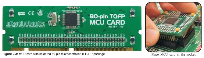
The new adapter card (left) and the old adapter card (right)
The new adapter largely solves those problems. You can connect a single row header and use it in a plug-in breadboard, and even though you only get half the IO pins this way it allows easy breadboard use that simply can't be done with the old adapter. For stripboard use it works perfectly with a single or double row header allowing MUCH faster project completion without needing a custom PCB. This is a powerful feature, and goes well with the other powerful feature of this edge socket that the PCB can be quickly plugged in to the BIGPIC6 to program the PIC.
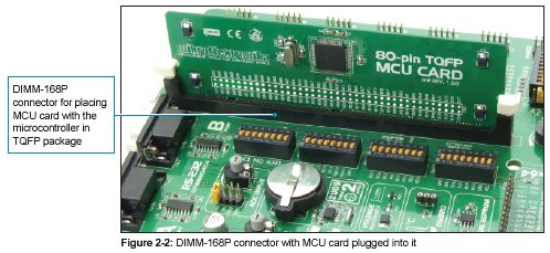
I'm sure this was a key part of the MikroE designers thought process. Solder a double row header on the adapter, and a double row header socket in stripboard for the final project. One-off industrial controllers etc that need a big PIC can be built quickly and reprogrammed easily, or even field swap the PIC because it is on a handy adapter card. For the next step up in commercial applications a proper DIMM-168P edge connector can be soldered into custom application PCB and the PIC adapter just plugged in as it does on the dev board.
So apart from the problem of the adapter being big (and it IS big!) its new design is better for hobby use, better for one-off construction and better for small quantity manufactured equipment where size is less important than being easily field swappable etc. And it's much easier to switch between PICs in a development environment too.
The two types of adapter boards (with PICs already soldered) are the same price ($19 to $21) although I believe MikroE have recently dropped the price from the old price of $24.90. The new $20 price is much more in line with a "consumable" item which is a good move since the new adapter board is much more convenient to actually USE in a finished project. The blank adapter board can be purchased for $8, which is competitive with most brands of 80pin TQFP adapter boards. But buying blanks now doesn't make a lot of sense since adapter + PIC + xtal, smd caps etc comes to about $16, then you have all that extra hassle of the SMD soldering and testing... For just $4 more you get a fully soldered and tested adapter PCB.
Using the BIGPIC6
Using it is a delight. The PCB layout is excellent considering how packed it is. It is a little hard to read the fine print and operate the control dipswitches which are close to the adapter PCB that sticks up quite high. Likewise the righthand column of pushbuttons (Rx0) is a little close to the GLCD if it is installed. The pushbuttons are the smaller type and are packed together but this doesn't seem to cause any problems. It is hard to find something to complain about!
The 67 LEDs are extremely bright and visible at even very low duty cycles like 1:256. Like my EasyPIC6 they are painfully bright looking directly at them like when reading the LED name to see which one is lit. These LEDs are so much better to use than the old LEDs on my BIGPIC4 because you can easily see low duty cycles and very short flashes.
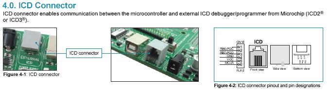
The BIGPIC6 has all the newer standard features for MikroE dev boards like built in backlight power for the LCD and GLCD and swichable safety resistor for the buttons in case you press a button when the PIC pin is driving it. It also has the new ICD connector (as well as its inbuilt PICFlash2 programmer). The ICD connector lets you program or debug the PIC using other hardware, (like a ICD2 ir PICKit2) but it also lets you use the BIGPIC6 as a ICSP programmer so it can program other PICs in external application boards!
Everything on the BIGPIC6 is clearly labeled, that means every dipswitch and every LED, every button, connector pin etc.
Even the bottom of the PCB is labeled on every solder joint in case you need to attach test probes etc.
A nice new feature that I have not seen before are the LCD and GLCD mounting frames. The GLCD one is especially useful when using the touchpanel on the display because you have to press on it! The mounting frames are long overdue, on my other board I have often jammed something under the LCDs to support them so they are not just hanging off the delicate header pins.
MikroE introduced the GLCD touch panel controller and ribbon socket on the EasyPIC5 and BIGPIC5, and this is still standard on the BIGPIC6. Although I have had GLCDs for years this is the first time I have played with a touch panel and I'm very excited by the possibilities.
The built in programmer works quickly and is seamlessly integrated into the MikroE compilers, but can also be called from within MPLAB if you prefer using the Microchip IDE. It's almost "boring" because it just does everything perfectly with never a problem. You just press F11 in the MikroC compiler, then the PIC is programmed and your application starts running.
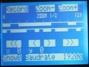
The full-colour manuals and schematic supplied in handy booklets are superb! I wish everything I bought had a manual as good as these. Heck I wish that I could write manuals this good for my own products! MikroE manuals are simple yet at the same time they contain all the important stuff in clear complete colour diagrams. Since they make manuals in many languages the manuals are more diagram oriented, and the extra effort has been put into the diagrams. They deserve extra credit for still supplying them in booklet form with every development board, even though they ALSO supply as electronic (PDF) on the CD that comes in the package. Here is one page;
Or here is the entire BIGPIC6 manual .PDF (10.7 Mb)
What additions/changes does the BIGPIC6 need?
Well the first suggestion is a no-brainer. Replace that silly little 1kbit eeprom with a 512kbit eeprom. There's only about $1 diference in price and 512 times more storage! I have replaced the one on my BIGPIC6 already, see the section below.
The second suggestion is also a no-brainer. Add a little piezo buzzer or little SMD speaker. Applications with LCDs and menus really benefit from a beep! All dev boards should have a buzzer or speaker.
I would like to see a xtal socket on the adapter card! There is plenty of room for one. The adapter comes with the default 10MHz xtal, for 10MHz or 40MHz PLL use. But some serial baud rates are only available at specific clock speeds, and if working with video generation or other signal generation it is nice to be able to use a specific xtal. Most of the other MikroE dev boards let you plug in a different xtal value at any time, and it is a real strength of their design. A 2-pin socket on the adapter would be easy and cheap, with solder pads near it to allow soldering a xtal in (if desired for reliability in final applications).
As for other changes... Since the adapter card is so big and has so much spare real estate, it would be really cool to put a parallel RAM on the adapter card and connect direct to the PIC pins. A benefit of 80 pin PICs is that you can afford to use 27 pins to manually drive a 128 kbyte static RAM which are cheap and common. Or add a SIPO shift register to drive the RAM with only 20 PIC pins. I'm not suggesting using the PIC's inbuilt module for external program memory (because that has limits and complications) but instead just connect a static RAM to the PIC pins and use manual RAM access. I would love a development board setup that had a lot of RAM! That would open up a ton of application opportunities and the only cost would be a slightly more expensive adapter card upgrade, which would be an optional accessory of course. And if you need to build a final application with RAM it's all ready on the adapter PCB!
I would bring back the SD/MMC card socket, no argument. Since that needs a 3.3v regulator it would also be good to make the 3.3v available on some connectors as a big PIC is likely to be connected to a lot of modern peripherals and more and more of them are using 3.3v. The SD card socket could go in the space to replace the port expander. The port expander has value but it's not the best use of real estate when the PIC already has 68 IO pins.
In the remaining space where the port expander used to be I would put 2 fast 8bit parallel DACs and 2 dip8 switches to connect the DACs to the PIC. The big PICs have heaps of ADC but no DACs so a couple of fast (not serial) DACs would be very handy and there are plenty enough PIC pins to drive them. OK, so not everybody wants fast DACs on a non-dsp PIC but there is a big difference between 19kHz PWM channels and two DACs outputting up to 1 megasample/sec each which is not unreasonable on a 10 MIPS PIC. The 8bit DACs could even be done as R2R networks (in SMD or SOIC) to keep costs down.
Modifying the BIGPIC6
I just HAD to replace the 1k eeprom with a 512k eeprom. Microchip make a 512k eeprom in the narrow (150mil) package, but I did not have one in stock so I bent the leads of a 208mil 24LC512 eeprom and used that. It looks a bit messy but that doesn't matter the job is done and I now have 512k onboard. :) A proper narrow package eeprom would be the right replacement.
Warning! I did this mod easily in 10 minutes but it requires skill at SMD rework. If you choose to do this you may damage your BIGPIC6! Be warned. And don't blame me.
The adventures of 512k Avenger!
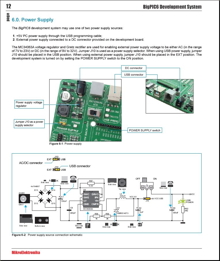
I will add a power supply switch instead of the EXT/USB jumper. My EasyPIC6 also needs this mod but I need to buy a couple of small neat switches that will fit the 0.1" 3-pin mount.
The other mod I am considering is to remove the SMD xtal on the adapter card and connect a 2-pin socket there. But this is not a rush, I can wait until I buy another adapter (I still need a 16F8720) and then I can modify both my developent adapters at the same time.
Overall opinion
Most of what I said before in my EasyPIC6 review also applies here, like the excellent hardware quality, superb manuals, great usability and fast reliable programmer etc etc.
But where the EasyPIC6 is perfect for PIC hobby development and pro development alike (just go and buy one!) the BIGPIC6 is much more specialised.
The BIGPIC6 can only be used with the big 80-pin PICs, and could never be justified as a beginner or entry level tool, and it would be a foolish choice as your only development tool. But these big PICs have a lot of power. They are quite "industrial" and it should not be instantly assumed that they are less of a controller than the dsp range PICs just because they are slightly older.
These PICs run at 5v, which might be considered obsolete if you are talking about little MP3 players but is still very important in industrial controllers especially when all the PIC IO pins are specced at 5v and 25mA (provided the total of port current is < 200mA). Likewise the big ROM of 128 kbyte (18F8720/8722) means these can run massive operating systems like industrial PLCs, command interpreters or even heaps of lookup table ROM for signal generation. And the 18F instruction set allows a lot of code re-usability and easier assembler coding than the dsp PICs.
The BIGPIC6 is definitely aimed at the pro developer who will sometimes need to create an application with tons of 5v IO pins, big ROM etc and can also take advantage of years already invested in 16F or 18F code. The new adapter cards are ideal for one-off or small quantity builds where you need to create something with a huge powerful PIC and get it built and soldered up in a hurry, and the $20 consumable cost for an adapter card with PIC is quite reasonable.
I really can't say whether this is a good dev board for hobby PIC use. If a hobbyist already has a lot of experience with 16F/18F PIC and would like to work on larger applications then it would be worth the investment in a BIGPIC6 and a few adapter cards. But then in a hobby environment where time is plentiful it may be a better idea to work with a dsp PIC instead (like dsPIC24 or 33 series), even though they are a lot fiddlier and there is less chance for code re-use or easy assembler work.
Obviously MikroE think the big PICs are important, they have upgraded the BIGPIC dev board to version 6 first while their dsPIC PRO 4 and lv24/33A boards remain the same. I agree with them, these big PICs are fast and easy to use but also pack a big punch with up to 128k ROM and a ton of 5v 25mA IO pins. From a pro developer side it is important to be able to take an existing product from a PIC 18Fxxx 40 pin and just "upgrade" it to a powerful 80 pin with the same source code and not have to fiddle about.
The BIGPIC6 is a superb piece of versatile development hardware that leaves very little for me to criticise. I think it is a fantastic companion to a EasyPIC6 and ideal for quickly developing commerical apps that need plenty of power and lots of PIC pins but don't require "digital signal processing" or 3.3v portable use.
But as for the question "should I buy a BIGPIC6 next?" that is going to remain a question that YOU have to answer, not me. I think you know MY answer. :)
Now for some BIGPIC6 projects!
I've put together a few BIGPIC6 projects;